CHAPTER 4 IMAGE FORMATION SYSTEM
COPYRIGHT
©
1999 CANON INC. CANON NP6512/6612/7120/7130/7130F REV.0 AUG. 1999 PRINTED IN JAPAN (IMPRIME AU JAPON)
4-7
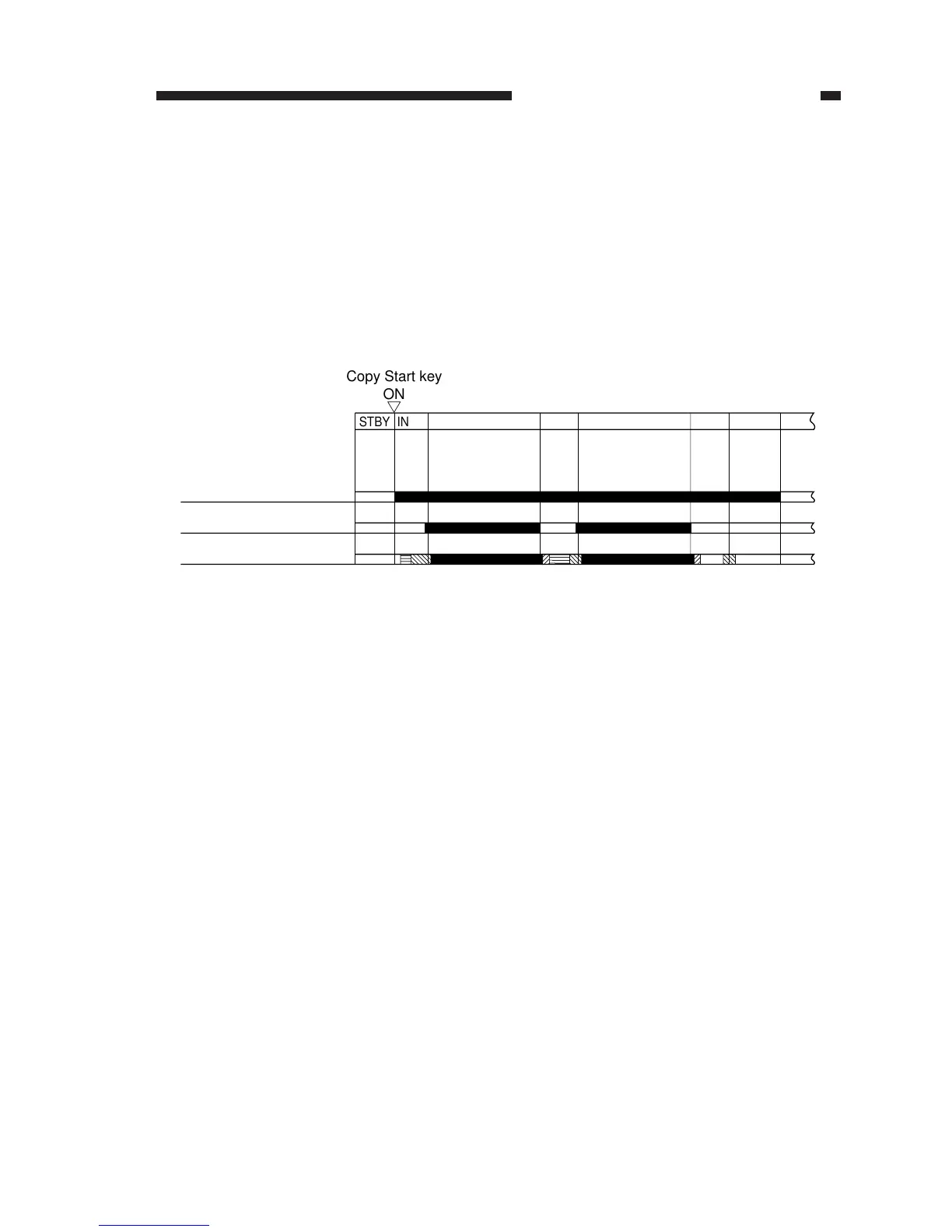
Figure 4-104
Copy Start key
ON
STBY INTR
SCFW SCFW
SCRV
LSTR
STBY
Main motor (M1)
Scanning lamp (LA1)
Primary bias
III
III IV
SCRV
c. Switching the DC Bias Level
The machine changes the level of its DC bias according to the following: copying image area,
sheet-to-sheet distance, and image trailing edge margin. In addition, it is also switched while a
cleaning bias is applied by the transfer roller, during which the primary charging roller applies a
negative DC bias to prevent the photosensitive drum from being charged to a positive potential.
The level of the DC bias is switched by the DC bias ON signal (serial) from the DC controller
PCB. In response to this signal, the microprocessor (Q900) on the composite power supply PCB
changes the DC bias control signal (PDC_PWM) to switch the level of the DC bias applied to the
primary charging roller. (See Table 4-102.)
I: Area between sheets
II: Cleaning area by transfer
III: Image area
IV: Trailing edge area
 Loading...