2-18
Step 4 Install the Camera
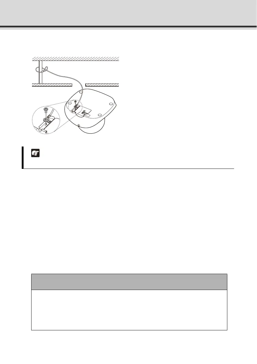
4. Affix the safety wire to the camera and also to the installation location (anchor or structure in
the ceiling, etc.).
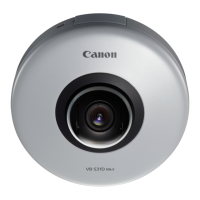
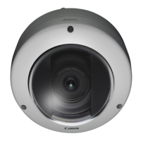
* The figure shows VB-C500D.
5. Connect each interface cable.
• This process is not required if you don't use any microphone, sensor, AC adapter or
external power supply.
• Select an appropriate interface cable according to the external device used, and
connect the cable to the camera.
• The interface cables and camera have dedicated connectors and connection
terminals, respectively.
• You can select a desired direction from which to take out the interface cables and
other wirings.
• For the types of interface cables, see "Optional Items" ( P. 1-21).
Note
The wire direction is different depending on how the camera is installed.
Note
When disconnecting/connecting the audio interface cable, I/O interface cable
and power interface cable, always do so by holding the connector.
When the audio input/output, external device input/output and external power
supply are used, do not use any cable other than the dedicated interface
cables. Damage may occur.



 To Next Page