2-22
Step 4 Install the Camera
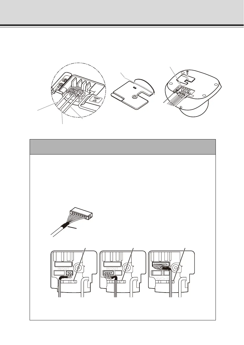
Wiring on a Ceiling
Cut out the side face of the cable cover with the V-shaped groove. Guide the interface cables
out towards the side face of the camera, and affix the cable cover with a screw.
Note
Connect each interface cable to its dedicated terminal and affix it into its specified
groove, as shown below.
At this time, make sure the heat-shrinkable tubes that protect the cables rest properly
in front of the affixing grooves.
If the cable is not properly installed, it may come off and cause the camera to
malfunction.
I/O interface cable
Power interface
cable
Audio interface cable
Cut out the side face of the cover.
Cut out the
V-shaped groove.
Affixing groove for cable Affixing groove for cableAffixing groove for cable
Power Audio I/O
Interface cable fixing method
Heat-shrinkable tube
for cable protection