2-23
Step 4 Install the Camera
Initial Setting and Installation of Camera
6. Connect the LAN cable, and also connect each external device using a cable.
Connect the LAN cable that has been guided through the wiring hole, to the LAN cable on the
camera side.
If necessary, connect the audio, I/O or power interface cable to each external device.
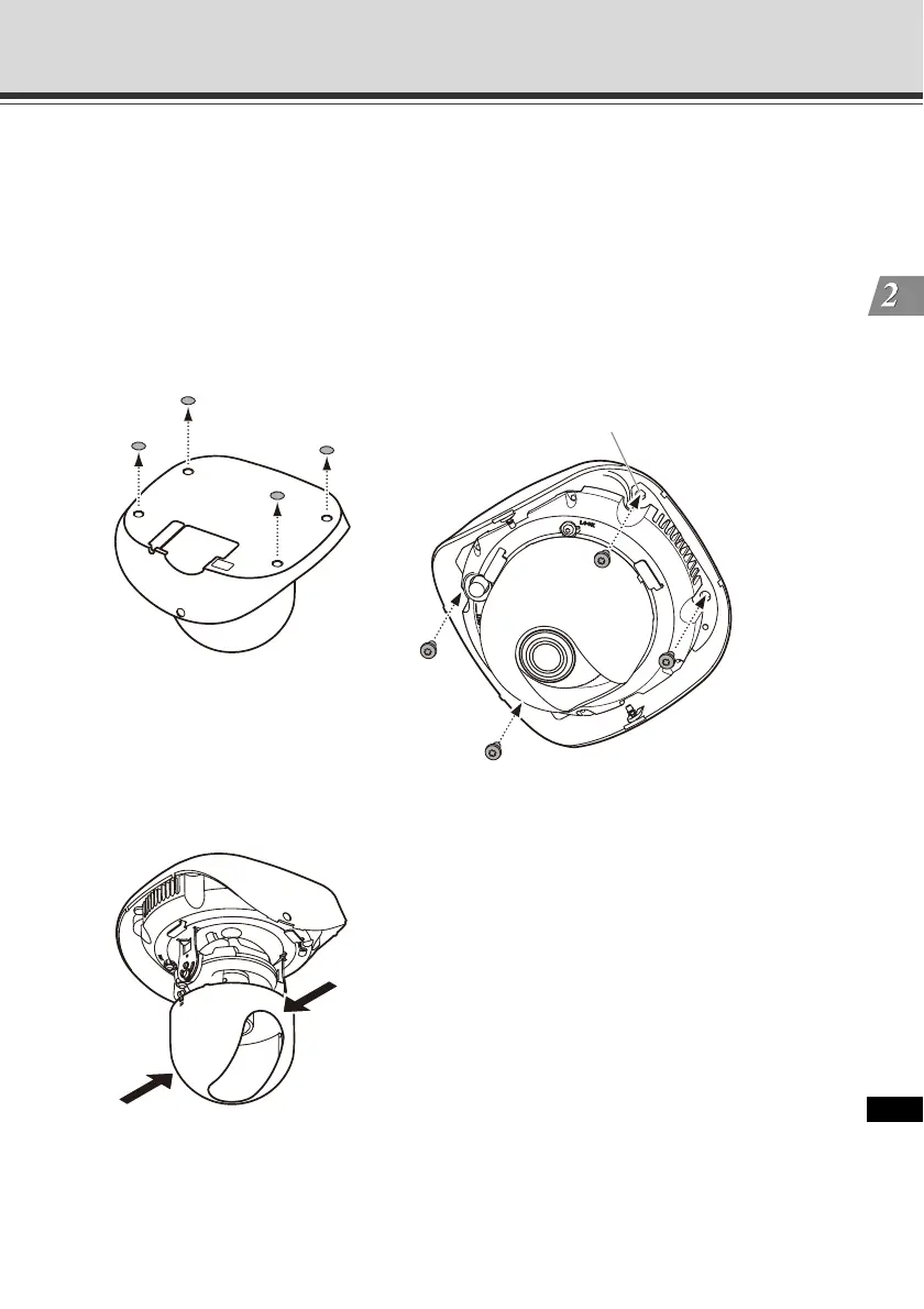
7. Affix the camera on the ceiling.
Remove the protection sticker from four camera mounting screw holes on the bottom of the
camera. Then, align the camera mounting screw wholes to the position marked in step 1 to
affix the camera.
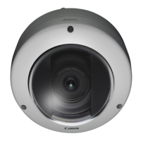
* The figure shows VB-C500D.
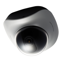
8. Push the inner cover in the direction of the arrow, as shown below, to remove the cover.
* The figure shows VB-C500D.
Screw holes
(4 locations, Φ4.6 mm (Φ0.18 in), M4.0)