15
ENGLISH
ir33 +030220441 - rel. 2.0 - 01.05.2006
5.1 Parameter copying key
Programming keys PSOPZKEY00/A0
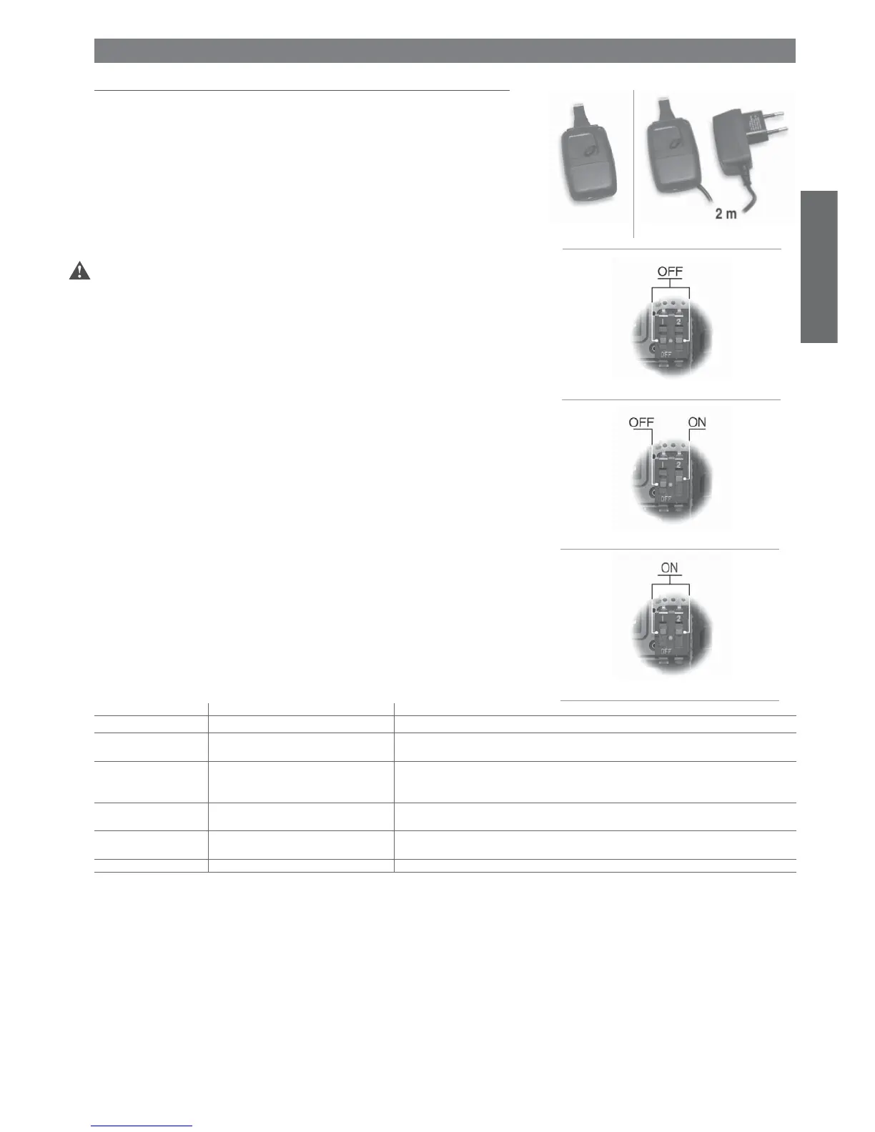
The programming keys PSOPZKEY00 (Figure 5.a) and PSOPZKEYA0 (Figure 5.b) are used to copy
the complete set of parameters relating to the CAREL ir33 controller parameters. The keys must be
connected to the connector (4 pin AMP) fi tted on the compatible controllers, and work even without
switching the controller on.
Programming keys IROPZKEY00/A0
The programming keys IROPZKEY00/A0, unlike the PSOPZKEY00/A0, with the use of the confi guration
kit PSOPZPRG00, can set up to seven different confi gurations of parameters inside the instrument. The
keys must be connected to the connector (4 pin AMP) fi tted on the controllers. The keys IROPZKEY00/
A0 can only be used with the controllers based on the IR33 platform. All operations must be performed
with the instrument off, unless otherwise indicated on the instruction sheet for the specifi c instrument.
Important:
PJOPZKEY00 to be used ONLY for PJ controllers;
- PSOPZKEY** to be used ONLY for powercompact/ir33, Mastercella, power-split, MGE controllers and
I/O modules.
Three functions are available, and are selected by using the two supplied dipswitches; these can be
accessed by removing the battery cover:
• load the parameters for a controller onto the key (UPLOAD - Fig. 5.c);
• copy from the key to a controller (DOWNLOAD - Fig. 5.d);
• extended copy from the key to a controller (EXTENDED DOWNLOAD - Fig. 5.e).
Warning: the parameters can only be copied between instruments with the same code. The UPLOAD
operation can, however, always be performed.
5.1.1 Copying and downloading the parameters
The following operations are used for the UPLOAD and/or DOWNLOAD or EXTENDED DOWNLOAD
functions, simply by changing the settings of the dipswitches to change the function:
1. open the rear cover on the key and position the 2 dipswitches according to the desired operation;
2. close the rear cover on the key and insert the key in the connector on the controller;
3. press the button and check the LED: red for a few seconds, then green, indicates that the operation
was completed correctly. Other signals or the fl ashing of the LED indicates that problems have
occurred: refer to the table below;
4. at the end of the operation, release the button, after a few seconds the LED goes OFF;
5. remove the key from the controller.
LED signal Cause Meaning and solution
Red LED fl ashing Batteries discharged at start copy The batteries are discharged, the copy operation cannot be performed. Replace the batteries.
Green LED fl ashing Batteries discharged during copy or at end of
copy
During the copy operation or at the end of the operation the battery level is low. Replace the batteries and
repeat the operation.
Red/green LED fl ashing
(orange signal)
Instrument not compatible The parameter set-up cannot be copied as the connected controller model is not compatible. This error
only occurs for the DOWNLOAD function; check the code of the controller and run the copy only for
compatible codes.
Red and green LEDs ON Error in data being copied Error in the data being copied. The instrument’s EEPROM is corrupted, and therefore the key cannot be
copied.
Red LED on steady Data transfer error The copy operation was not completed due to a serious error when transferring or copying the data. Repeat
the operation, if the problem persists check the key connections.
LEDs OFF Batteries disconnected Check the batteries.
Notes:
1. at the start and the end of the UPLOAD and DOWNLOAD operations (normal or extended), the
buzzer on the instrument will emit an audible signal;
2 the DOWNLOAD operation (normal or extended) is possible even if the operating parameters and
controller are incorrect. If there is an error in the unit parameters, these will be recovered by the
key. Be careful when recovering the unit parameters from a key, as these determine the low-level
operation of the controller (unit model, type of interface, assignment of logical relay to physical relay,
brightness of the display, level of modulation of the relay control signal …).
The unit parameters from the original model must therefore be restored to ensure the correct operation
of the controller.
5. ACCESSORIES
Fig. 5.a
Fig. 5.b
Fig. 5.c
Fig. 5.d
Fig. 5.e
UPLOAD
DOWNLOAD
EXTENDED DOWNLOAD
Tab. 5.a