36
rd
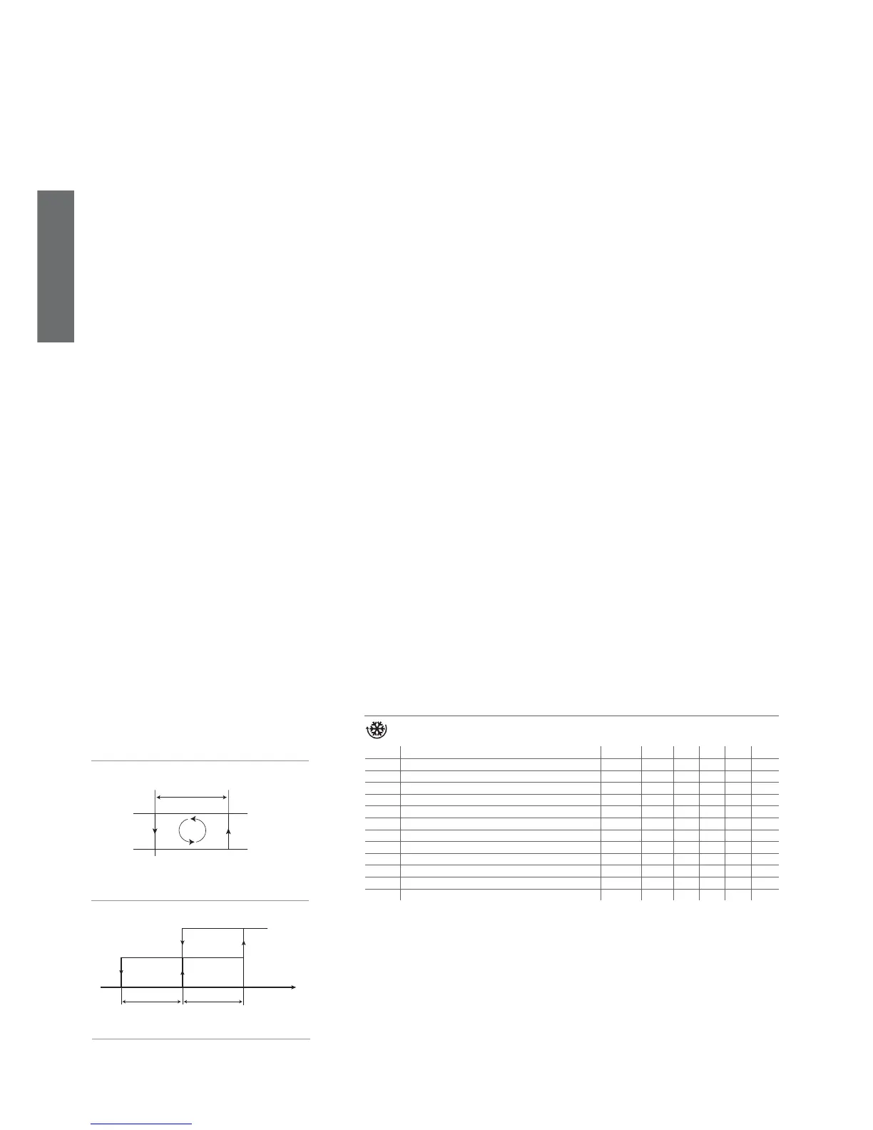
Set Point
OFF
ON
DIRECT Freddo
attuatore
D
St
rd/2 rd/2
Sonda virtuale
Direct
ENGLISH
ir33 +030220441 - rel. 2.0 - 01.05.2006
Fig. 7.b
Fig. 7.a
/A2: Confi guration of probe 2
Used to confi gure the operating mode of probe 2.
/A2= 0 => probe 2 absent
/A2= 1 => product probe (used for display only)
/A2= 2 => defrost probe
/A2= 3 => condenser probe
/A2 = 4 => antifreeze probe
In any case, probe 2 is used for calculating the virtual control probe.
Default: /A2= 2 => defrost probe; /A2= 0 on model S => probe 2 absent.
/A3: Confi guration of probe 3
As above, but relating to probe 3.
Important note: the input is enabled for use with a probe only if the parameter corresponding to digital
input A4 is set to 0.
Default: /A3= 0 => Probe 3/Digital input absent.
/A4: Confi guration of probe 4
As above, but relating to probe 4, if fi tted.
Important note: the input is enabled for use with a probe only if the parameter corresponding to digital
input A5 is set to 0.
Default: /A4 = 0 => Probe 4/Digital input absent.
/A5: Confi guration of probe 5
As above, but relating to probe 5, if fi tted.
Important note: the input is enabled for use with a probe only if the parameter corresponding to digital
input A9 is set to 0.
Default: /A5 = 0 => Probe 5/Digital input absent.
Note: if more than one probe is confi gured with the same operating mode, the controller will consider, for
the operating mode in question, the fi rst probe in increasing order from 2 to 5 with this confi guration.
Example: if there are two condenser probes confi gured, /A3=3 and /A5=3, the controller will manage
the alarm algorithm with reference to probe 3.
/C1: Calibration or offset for probe 1
/C2: Calibration or offset for probe 2
/C3: Calibration or offset for probe 3
/C4: Calibration or offset for probe 4
/C5: Calibration or offset for probe 5
These parameters are used to correct the temperature measured by the probes, using an offset: the
value assigned to these parameters is in fact added to (positive value) or subtracted from (negative
value) the temperature measured by the probes. The temperature value is corrected by the offset before
checking if the reading is out-of-range.
Example: to decrease the temperature measured by probe 1 by 2.3 degrees, set /C1= -2.3. The calibra-
tion or offset can be set from -20 to +20.
Warning: if the probe is disabled, the display shows ‘___’. If the probe is faulty, the display shows the
corresponding error code.
When displaying the parameter, pressing SET shows the value of the corresponding probe already
corrected with the offset, while pressing SET a second time displays the abbreviated code.
Default: /C1=/C2=/C3=/C4=/C5=0 no offset.
7.2 Temperature control parameters
Code Parameter MSYF ** UOM Type Min Max Def.
St Temperature set point MSYF °C/°F F r2 r1 0.0
rd Control delta -SYF °C/°F F 20 0.1 2.0
rn Dead band -SYF °C/°F C 60 0.0 4.0
rr Reverse differential for control with dead band -SYF °C/°F C 20 0.1 2.0
r1 Minimum set point allowed MSYF °C/°F C r2 -50 -50
r2 Maximum set point allowed MSYF °C/°F C 200 r1 60
r3 Operating mode -SYF fl ag C 2 0 0
r4 Automatic night-time set point variation MSYF °C/°F C 20 -20 3.0
r5 Enable temperature monitoring MSYF fl ag C 1 0 0
rt Temperature monitoring interval MSYF hours F 999 0 -
rH Maximum temperature read MSYF °C/°F F - - -
rL Minimum temperature read MSYF °C/°F F - -
Tab. 7.c
St: set point
Establishes the set point value used by the controller. Default: St=0.0.
rd: Control delta
Establishes the value of the differential, or hysteresis, used for temperature control. Low values guarantee
an ambient temperature that deviates only slightly from the set point, but involves frequent starts and
stops of the main actuator (normally the compressor).
In any case, the compressor can be protected by suitably setting the parameters that limit the number of
activations/hour and the minimum OFF time (see the C parameters).
Note: if control with two compressor steps has been selected (‘H1’=12, 13), the differential ‘rd’ is divided
between the two steps.
Default: rd =2