38
accensione strumento
power ON
ON
ON
OFF
ON
OFF
OFF
C0
richiesta di intervento
insertion request
compressore
compressors
ON
ON
OFF
OFF
C1
richiesta inserimento
insertion request
compressore
compressors
ON
ON
OFF
OFF
C2
richiesta inserimento
insertion request
compressore
compressors
ON
ON
OFF
OFF
C3
richiesta inserimento
insertion request
compressore
compressors
ON
OFF
C4
compressore
compressors
OFF = 15 min.
Fig. 7.d
Fig. 7.e
Fig. 7.f
Fig. 7.g
Fig. 7.h
ENGLISH
ir33 +030220441 - rel. 2.0 - 01.05.2006
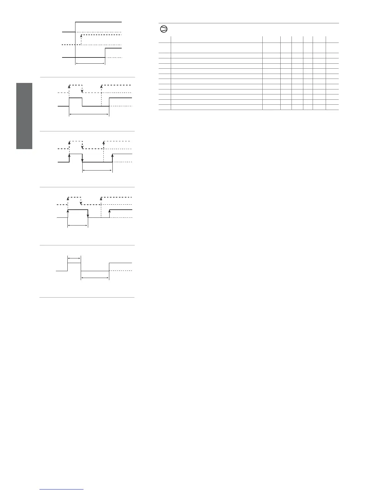
7.3 Compressor management parameters
Code Parametro MSYF ** U.M. Type Min Max Def.
c0 Compressor, fan and AUX start delay on power up in
dead zone
-SYF min C 0 15 0
c1 Minimum time between successive starts -SYF min C 0 15 0
c2 Minimum compressor OFF time -SYF min C 0 15 0
c3 Minimum compressor ON time -SYF min C 0 15 0
c4 Duty setting -SYF min C 0 100 0
cc Continuous cycle duration -SYF hours C 0 15 0
c6 Alarm bypass after continuous cycle -SYF hours C 0 15 2
c7 Maximum pump down time -SYF s C 0 900 0
c8 Comp. start delay after open PD valve -SYF s C 0 60 5
c9 Enable autostart function in PD -SYF fl ag C 0 1 0
c10 Select pump down by time or pressure -SYF fl ag C 0 1 0
c11 Second compressor delay -SYF s C 0 250 4
Tab. 7.d
c0: Compressor and fans start delay (if ‘FAN’ relay present) on start-up
When the controller is switched on, the compressor and the evaporator fans and the auxiliary relay in
control with dead band (H1=11) start after a delay (in minutes) equal to the value set for this parameter, in
order to protect the compressor against repeated power-ups in the event of frequent power drops. Default:
c0=0 => no minimum delay is set.
Example: setting c0=6 forces the compressor to wait 6 minutes before starting from when power
returns. In the event of systems with more than one compressor, the parameter c0 can also be used
to avoid simultaneous starts of a series of units. Simply set a different value of c0 for each compressor.
Note: the second compressor step, for the aux1 output (‘H1’=12, 13), is associated with the timers ‘c0’,
‘c1’, ‘c2’, ‘c3’.
c1: Minimum time between two successive starts of the compressor
Sets the minimum time (in minutes) that must elapse between two starts of the compressor, irrespective of
the temperature and the set point. Setting this parameter limits the number of starts per hour.
Default: c’=0 => no minimum time is set between two starts.
Example: if the maximum number of activations/hour allowed is 10, simply set c1=6 to ensure that this
limit is respected. Note: the second compressor step, for the aux1 output (‘H1’=12, 13), is associated
with the timers ‘c0’, ‘c1’, ‘c2’, ‘c3’.
c2: Minimum compressor OFF time
SSets the minimum time (in minutes) for the compressor to remain OFF. The compressor is not started
again until the minimum time selected (c2) has elapsed from when it last stopped.
Note: this parameter is useful to ensure the balancing of the pressure after the compressor stops for
systems with hermetic and capillary compressors. The second compressor step, for the aux1 output
(‘H1’=12, 13), is associated with the timers ‘c0’,‘c1’,‘c2’,‘c3’.
c3: Minimum compressor ON time
Sets the minimum running time for the compressor. The compressor is not stopped until it has been
ON for at least the minimum time selected (c3). Note: the second compressor step, for the aux1 output
(‘H1’=12, 13), is associated with the timers ‘c0’,‘c1’,‘c2’,‘c3’.
Default: c3=0 => no minimum running time is set.
c4: Duty setting
If the virtual control probe fault alarm occurs (see parameter ‘/4’), this parameter is used to ensure the
operation of the compressor until the fault is resolved.
Default: c4=0 => compressor always Off in the event of a virtual control probe error.
Important: In the event of errors on probe 2, the virtual probe corresponds to the room probe (probe
1) and consequently the Duty Setting is not activated.
In practice, as the compressor is no longer able to operate based according to the temperature (due to
the probe fault), it is made to run cyclically with an operating time (ON time) equal to the value assigned
to parameter c4 (in minutes) and a fi xed OFF time of 15 minutes.
There are two values of c4 that cause special behaviour:
c4=0, in the event of faults involving the virtual control probe, the compressor is always OFF;
c4=100, the compressor is always ON, that is, the 15 minute OFF time is always ignored.
Special situations:
• if the virtual control probe error occurs while the compressor is OFF, it remains OFF for 15 minu-
tes, and is then started (respecting the times set for parameters c1 and c2) and remains ON for a
time equal to c4, Duty Setting. This special operation is signalled by the LED that fl ashes during the
compressor OFF period, and remains on steady when the compressor is operating. The fans continue
to operate according the set parameters (see F parameters). If the duty setting requires the immediate
shut-down of the compressor for a non-specifi ed time (c4= 0), this is done without observing the
compressor protection times.
• if the virtual control probe error occurs while the compressor is ON, it remains ON for the time c4, and
then is stopped (without observing the minimum ON time, if set for parameter c3) and remains OFF
for 15 minutes (the LED fl ashes in this phase).
After this, cyclical operation starts, with an operating time equal to the value of c4).
Warning: If the probe error disappears, the unit returns to normal operation.
Note: if control with two compressor steps is selected (with or without rotation, ‘H1’= 12 or 13), the duty
setting acts on both steps.