29
St
Grandezza controllata
R
REVERSE
rr rn rd
D
DIRECT
zona di non
intervento
==
St
Temperatura
R
rr
rd
rnrn/2 rn/2
R
ENGLISH
ir33 +030220441 - rel. 2.0 - 01.05.2006
Fig. 6.d
Fig. 6.e
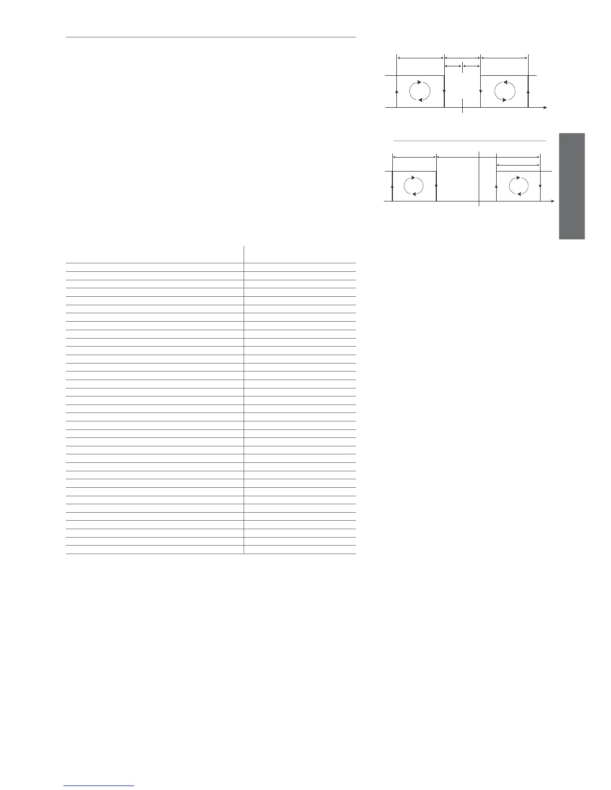
6.11 Control with dead band
Control with dead band can be activated by using the aux1 output for the reverse step: H1=11. The set
point ‘St’ is in the centre of the dead band.
The parameter ‘rd’ represents the control differential associated with the compressor, ‘rn’ the size of the
dead band, ‘rr’ the differential for reverse control associated with the aux1 output. The diagram in Figure
6.d shows control with dead band in the case of direct operating mode (‘r3’=0 and 1).
The dead band is mainly used in direct operating mode. The diagram in Figure 6.e shows control with
dead band in the case of reverse operating mode (‘r3’=2).
The step associated with the aux1 output remains in reverse. The step associated with the compressor
output passes from direct to reverse.
Note:
1. the step associated with the aux1 output is only associated with the protection timer ‘c0’, while the
step associated with the compressor (in both direct and reverse) is associated with the timers ‘c0’ ‘c1’
‘c2’ ‘c3’. As a result, the steps may be active at the same time due to the protectors associated with
the compressor step (minimum on time), as well as the unit defrost status.
2. if the curtain switch function is enabled (‘A4’=7), the controller modifi es the set point when the con-
tact closes, adding or subtracting the value of parameter ‘r4’; the new value is used for all functions
relating to the set point (e.g. relative high and low temperature alarms, dead band, etc.). When
‘r4’=3.0 (preset value) the set point is increased by 3 degrees compared to the value used with the
curtain open in direct mode, and decreased by 3 degrees in reverse mode. The rotation of the loads
is not envisaged in reverse operating mode (‘r3’=2). The following table defi nes the status of the
reverse output (aux1) in control with dead band.
Function active Reverse output in control with dead
band
Normal direct or reverse-cycle control Normal operation
Remote off, from supervisor or keypad Reverse output deactivated
Defrost Normal operation
Continuous cycle Reverse output deactivated
Temperature alarm monitoring Normal operation
Evaporator fan control Normal operation
Power on Normal operation
Normally-open or normally-closed alarm output Normal operation
Auxiliary output Normal operation
Light output Normal operation
Second evaporator output Normal operation
Control output for pump down valve Normal operation
Condenser fan control output Normal operation
Second delayed compressor output Normal operation
Auxiliary output with switch off Normal operation
Light output with switch off Normal operation
No function associated with the AUX output Normal operation
Reverse output in control with dead band -
Second compressor step output Normal operation
Second compressor step output with rotation Normal operation
Door switch with compressor, fan off and light management Normal operation
Door switch with compressor off and light management Normal operation
Curtain switch with set point variation and light management Normal operation
Light sensor and light management Normal operation
Auxiliary output activation switch Normal operation
Door switch with compressor, fan off, no light management Normal operation
Door switch with compressor off, no light management Normal operation
Light activation from keypad or supervisor Normal operation
Auxiliary activation from keypad or supervisor Normal operation
Alarms See table of alarms and signals
Virtual control probe alarm Reverse output deactivated
Product probe alarm Normal operation
Defrost probe alarm Normal operation
Condenser probe alarm Normal operation
Antifreeze probe alarm Normal operation
Tab. 6.l