17
Fig. 5.l
Fig. 5.m
Fig. 5.n
Fig. 5.o
Fig. 5.p
Fig. 5.q
ENGLISH
ir33 +030220441 - rel. 2.0 - 01.05.2006
5.3 RS485 serial interface
The RS485 serial card option (IROPZ48500), shown in Figure 5.l, allows the ir33 instrument to be con-
nected to the RS485 serial network for supervision. In addition, the serial interface option IROPZ485S0 is
available, with automatic recognition of the polarity (+ and -).
For further details, refer to the corresponding instruction sheet.
5.4 Programming kit
This accessory interfaces the IROPZKEY00 programming key with any PC; this useful tool can be used to
program the key using the standard instrument parameters, and save the different confi gurations to fi les
that can be recalled during fi nal programming.
For the new generation instruments, such as powercompact and ir33, the user can change the password,
hide the parameters, change the level of visibility (with password protection or direct access) and, most
importantly, assign the output relays according to the confi guration of the utilities.
5.5 Transformers (ir33, power, DIN)
The transformers are used to convert mains voltage to the power supply voltage specifi ed for the ir33
and ir33DIN series controllers. Their compactness and sound design (winding immersed in plastic)
mean they can be used in all types of applications.
Code: TRA12VDE00: Transformer, 3VA 240/12VAC VDE - 153/M
5.6 RS485 serial board (DIN)
The IROPZSER30 board is used to connect the ir33DIN via the RS485 network serial to the PlantVisor su-
pervisory system (using the removable terminal supplied), as well as direct connection of the instrument
to the repeater display using a PSTCON**B00 cable.
5.7 RS485 serial board (MasterCella)
The IROPZSEM10/30 boards are used to connect the mastercella via the RS485 network serial to the
PlantVisor supervisory system. The IROPZSEM30 board also allows the repeater display to be connected
directly to mastercella using a PSTCON**B00 cable.
Codes:
• IROPZSEM10: RS485 serial board;
• IROPZSEM30: RS485 serial board + repeater display connection.
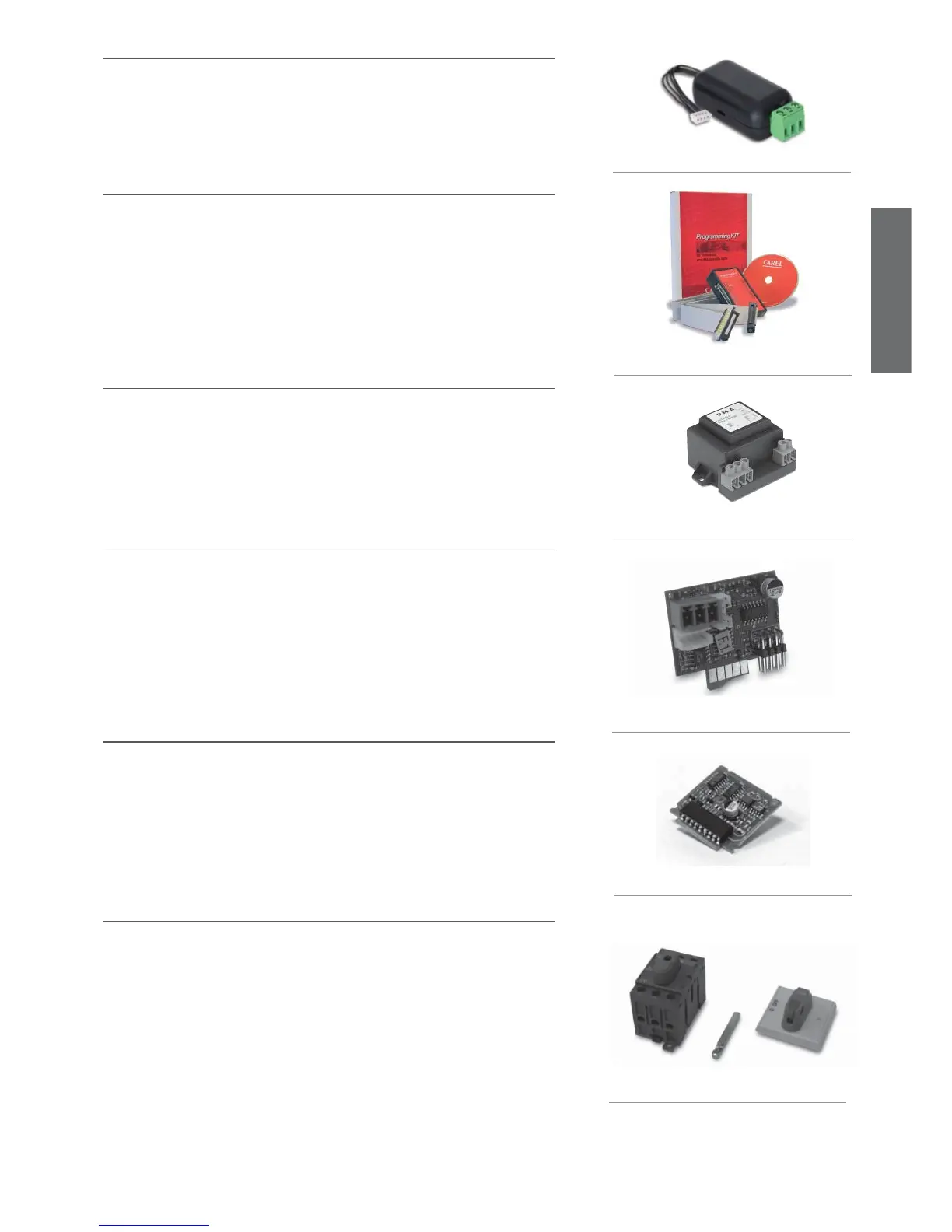
5.8 Door interlock (MasterCella)
Mastercella can be installed with a door interlock disconnecting switch, rated to 32 A, for the complete
on/off management of all the units; this device allows the system to be locked in the “Off” position so
that service operations can be performed in complete safety.
Codes:
• 0402512CEL, 32 A disconnecting switch;
• 0402515CEL, shaft H=85mm;
• 0402517CEL, switch with yellow/red indicator.