20
ENGLISH
ir33 +030220441 - rel. 2.0 - 01.05.2006
6.3 Switching the controller ON and OFF
The unit can be switched ON/OFF from a number of sources; supervisor and digital input. In this opera-
ting mode, the display will be show the temperature selected for parameter /tI, alternating with the OFF
message. The digital input can be used to switch the controller on/off, setting parameter A4/A5 to “6”.
Switching on/off from digital input has priority over the same function from the supervisor.
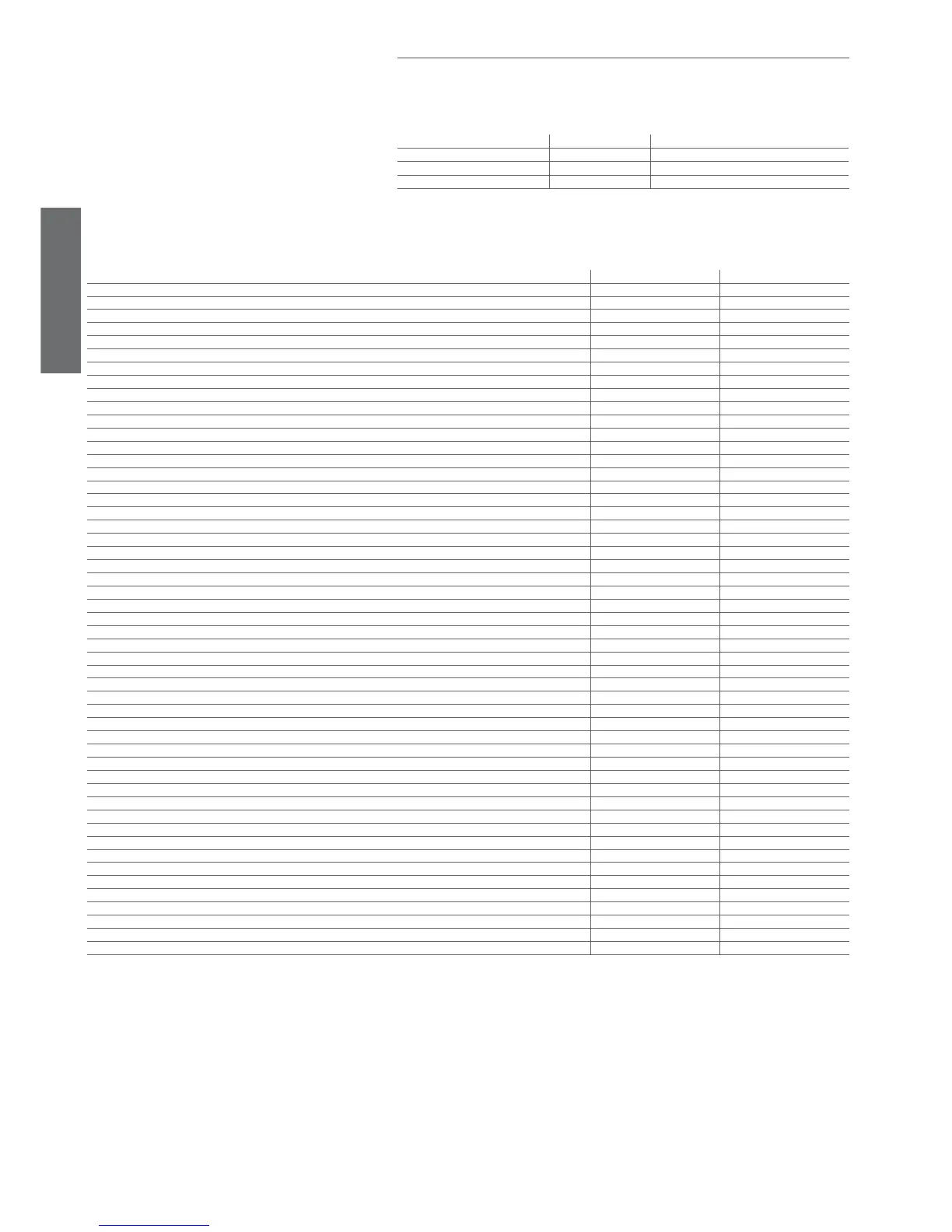
Origin Priority Note
Digital input Priority 1
Disable On/Off from keypad and supervisor
Keypad Priority 2
Supervisor Priority 3
Tab. 6.c
Important: if there is more than one digital input selected as the On/Off function (A4 and A5 = 6), the
ON status will be activated when all the digital inputs are closed. If event one contact is open, the unit is
switched OFF.
Function Enabled Disabled
compressor control (pump down valve OFF and shut)
9
AUX control (H1= 11) with dead band
9
second compressor step control with and without rotation (H1= 12, 13)
9
defrost (cyclical and manual)
9
fan control
9
fan control at low relative humidity (if enabled)
9
continuous cycle
9
condenser fan control (if enabled)
9
low temperature alarm (LO, alarm reset, and monitoring initialised)
9
high temperature alarm (HI, alarm reset, and monitoring initialised)
9
immediate alarm from external contact (IA, alarm reset and monitoring initialised)
9
delayed alarm from external contact (dA, alarm reset and monitoring initialised)
9
defrost ended due to timeout alarm (Ed1 and Ed2, alarm reset)
9
pump down ended due to maximum time alarm (Pd, alarm reset)
9
low pressure from external contact alarm (LP, alarm reset and monitoring initialised)
9
autostart alarm in pump down (AtS, alarm reset and not displayed)
9
pre-alarm: high condenser temperature (cht, alarm reset, and monitoring initialised)
9
high condenser temperature alarm (Cht, alarm reset, and monitoring initialised)
9
door open for too long alarm (dor, alarm reset)
9
antifreeze alarm (AFr, alarm reset)
9
HA HACCP alarm (alarm reset, and monitoring initialised)
9
HF HACCP alarm (alarm reset, and monitoring initialised)
9
buzzer (OFF) and alarm relay (non-alarm status)
9
HACCP control
9
defrost according to programmed time bands
9
defrost according to compressor running time (if enabled)
9
defrost from digital input (if enabled)
9
defrost from keypad and supervisor
9
defrost started from digital input (if enabled)
9
direct/reverse from digital input (if enabled).
9
modifi cation and display of frequent and confi guration parameters and the set point
9
ON/OFF auxiliary relay 1 (set as LIGHT or AUX)
9
select the probe displayed (model M only)
9
compressor autostart in pump down (if enabled)
9
door switch (with fan and compressor shutdown) limited to light management
9
remote ON/OFF
9
curtain switch, limited to light management
9
door switch (with fan shutdown only) limited to light management
9
management of the light sensor
9
updating of the defrost interval timer “dI”
9
control probe error (rE)
9
probe 1 error (E0)
9
probe 2 error (E1)
9
probe 3 error (E2)
9
probe 4 error (E3)
9
probe 5 error (E4)
9
clock alarm (Etc)
9
EEPROM alarm, unit parameters (EE)
9
EEPROM alarm, operating parameters (EF)
9
light or AUX on/off based on the set time bands
9
modifi cation of the set point based on the set time bands
9
Tab. 6.d
Note: In the OFF status, the defrost interval ‘dI’ is always updated, to maintain the regularity of the interval. If a defrost interval expires during the OFF status, this event is saved and, when
controller is switched back ON, a defrost request is generated.
The controller switches from ON to OFF with the following sequence:
• the compressor protection times are observed;
• the pump down procedure is performed (if enabled);
• the defrost is forced OFF and will not resume when switched back ON;
• the continuous cycle is forced OFF and will not resume when switched back ON.
The controller switches from OFF to ON with the following sequence:
• the compressor protection times are observed;
• the defrost on start-up (if enabled) is not performed, as this in fact refers to power-up;
• the compressor and fan delays on start-up are not set.
OFF status: