43
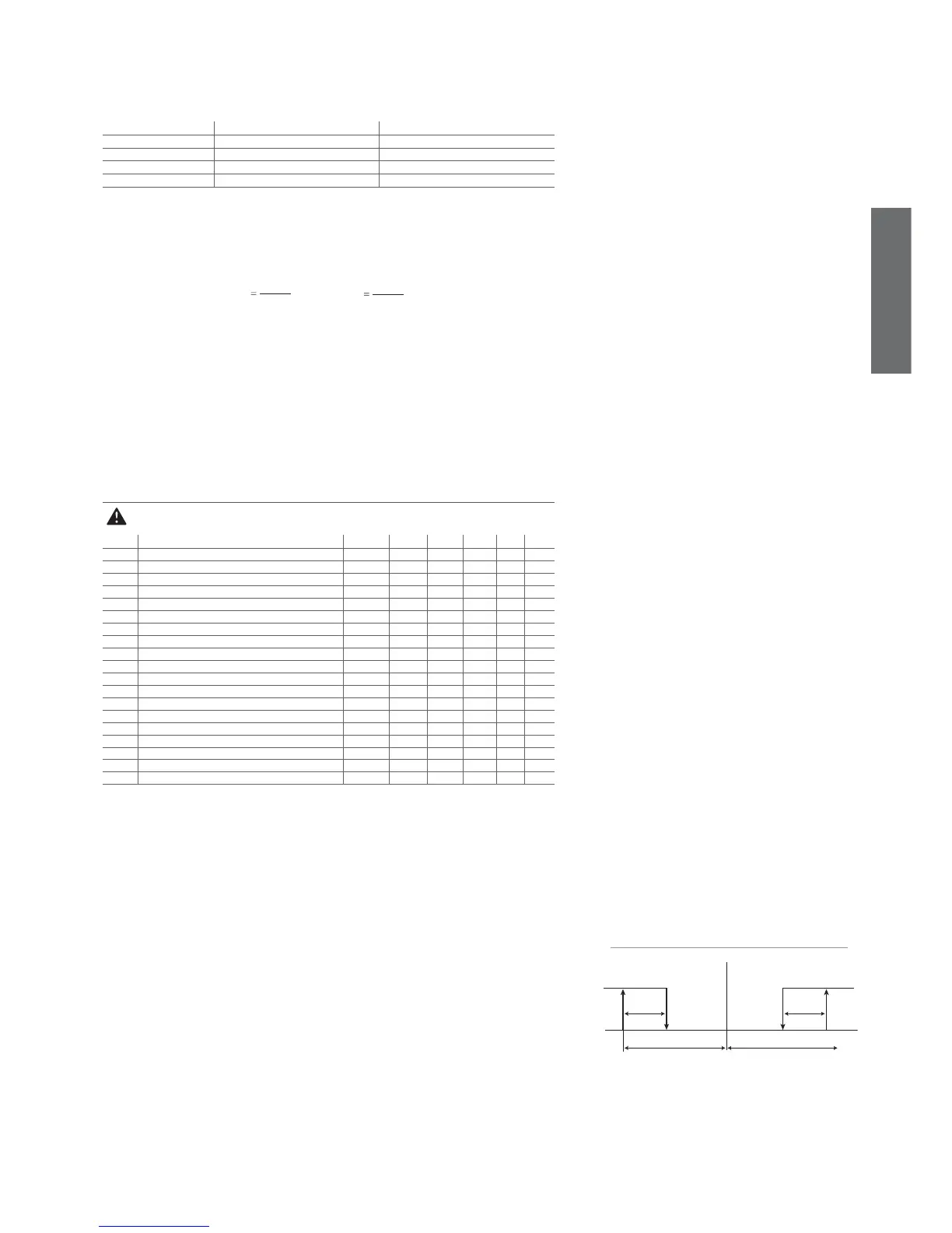
set point
allarme bassa temperatura allarme alta temperatura
A0
A0
AL
Fig. 7.i
ENGLISH
ir33 +030220441 - rel. 2.0 - 01.05.2006
d11: Running time temperature threshold
This parameter indicates the evaporation temperature below which the compressor must continue to operate
for the time d10 in order to generate a defrost request. Default: d11 =1 => 1°C.
d12: Advanced auto-adapting defrosts
This parameter is used to enable and disable the advanced defrost function, as per the following table:
d12 Skip defrost Automatic variation of dI
0 Disabled Disabled
1 Disabled Enabled
2 Enabled Disabled
3 Enabled Enabled
Tab. 7.f
Default: d12 =0 => Both the functions are disabled.
dn: Nominal defrost duration
This indicates the average duration of the defrost in normal operating conditions. It is expressed as a
percentage, with reference to parameters dP1 and dP2, according to the following formulae:
dn1 dP1
100
dn
and
dn2 dP2
100
dn
Example: with dn=65, dP1=90 min. and dP2=120 min.
Nominal defrost duration on main evaporator: 59 min.
Nominal defrost duration on auxiliary evaporator: 78 min.
Default: dn=65 => 65% of dP1 or dP2
dH: Proportional factor in the variation of the defrost interval
This parameter is used to increase or decrease the infl uence of the effective duration of the defrost, in
relation to the nominal duration, in the algorithm that manages the automatic variation of the defrost
interval. By setting dH=0, the effective duration has no infl uence on the duration of the defrost interval.
Vice versa, dH = 100 achieves maximum effi ciency. Default: dH=50
7.5 Alarm management parameters
Code Parameter MSYF ** UOM Type Min Max Def.
A0 Alarm and fan differential MSYF °C/°F C 0.1 20 2.0
A1 Type of threshold AL and AH MSYF fl ag C 0 1 0
AL Low temperature alarm threshold MSYF °C/°F F -50 200 0.0
AH High temperature alarm threshold MSYF °C/°F F -50 200 0.0
Ad Low and high temperature signal delay MSYF min F 0 250 120
A4 Digital input 1 confi guration -SYF - C 0 14 0
M--- - C 0 14 3
A5 Digital input 2 confi guration MSYF - C 0 14 0
A6 Stop compressor from external alarm -SYF min C 0 100 0
A7 External alarm detection delay -SYF min C 0 250 0
A8 Enable alarms Ed1 and Ed2 -SYF fl ag C 0 1 0
A9 Digital input 3 confi guration - C 0 14 0
Ado Light management mode with door switch MSYF fl ag C 0 1 0
Ac High condenser temperature alarm -SYF °C/°F C 0.0 200 70.0
AE High condenser temperature alarm differential -SYF °C/°F C 0.1 20 5.0
Acd High condenser temperature alarm delay -SYF min C 0 250 0
AF Light sensor OFF time -SYF sec C 0 250 0
ALF Antifreeze alarm threshold MSYF °C/°F C -50 200 -5.0
AdF Antifreeze alarm delay MSYF min C 0 15 1
Tab. 7.g
Note: par. A9 refers to the instruments with 5 relays (ir33DIN, powercompact and MasterCella).
Important warning: for the set times to become immediately operational, the instrument needs to be
turned off and on again. If this operation is not carried out, timing resumes operation the next time it is
used.
A0: Alarm and fan differential
This is the differential used for disabling high and low temperature alarms (AL and AH - see Figure
7.i) and for managing the fans (see the F parameters). In the event of an alarm, as can be seen from
the fi gure, the value of A0 in part determines the effective activation points of the temperature alarms.
Default: A0=2.0 degrees.
A1: Type of threshold AL and AH
Used to select whether the values of parameters AL and AH are considered absolute thresholds or
relative to the value of the set point.
A1 = 0 => AL and AH are considered as relative thresholds.
A1 = 1 => AL and AH are considered absolute thresholds.
Default: A1 = 0 => AL and AH are considered relative thresholds.
AL : Minimum temperature alarm
This is used to determine the activation threshold for the low temperature alarm.
Relative threshold for low temperature alarm = (set point) - (value of AL)
AL=0 => Alarm disabled;
Absolute threshold for low temperature alarm = value of AL.
AL=-50 => Alarm disabled.
Important: If the threshold AL is selected as relative, the value for disabling the alarm is 0, while if
selected as absolute, the alarm disabling value is -50.