18
ir33
powercompact
powercompact small
IROPZDSP00
PSTCON0**B0
IR00R*0000
PSTCON0**00
IR00R*0000
IROPZSEM30
MasterCella
ir33 DIN
PSTCON0**B0
IR00R*0000
IROPZSER30
Fig. 5.r
Fig. 5.s
Fig. 5.t
Fig. 5.u
Fig. 5.v
ENGLISH
ir33 +030220441 - rel. 2.0 - 01.05.2006
Fig. 5.s
Fig. 5.t
Fig. 5.u
Fig. 5.v
Fig. 5.r
5.9 Terminals (MasterCella)
This accessory is used to group together the neutral, live and earth connections on a single board instal-
led inside the mastercella. There are two models available: with 3 and 5 rows of terminals. In particular,
the second accessory allows direct access with the cables from the loads (live, neutral and earth) to this
board alone, thus avoiding having to make the connections during installation to the support terminal
block on the mastercella.
Codes:
• MDOPZCA000, 3 sets of connections;
• MDOPZCB000, 5 sets of connections.
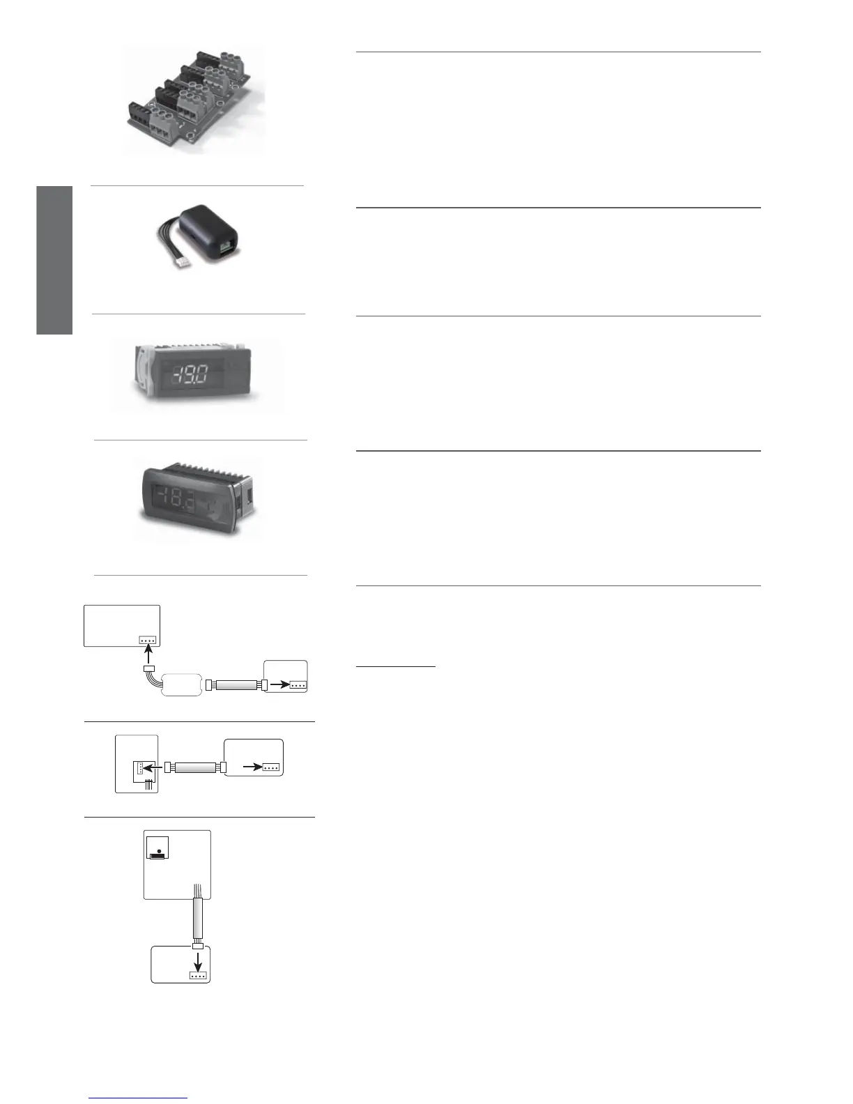
5.10 Repeater display interface option
The repeater display interface option (IROPZDSP00), shown in the fi gure below, allows the ir33 to inter-
face with a repeater display (IR00R*0000) to show the temperature measured by the third probe.
For further details on the connection, refer to the specifi c instruction sheet.
5.11 IR00R*0000 display terminal
This can be connected in parallel with the interface for setting the parameters. It displays the tempera-
ture read by the third probe installed in the hottest point of the cabinet, as required by the EN 441-13
standard.
Codes:
IR00RG0000 = ir33 green repeater display;
IR00RG0000 = ir33 red repeater display
5.12 PST00VR100 display terminal (powercompact)
Same as for the IR00R*0000.
5.13 Optional interface-repeater display connection cable
The connection cables between the interface and the repeater display have the following codes:
for ir33, ir33 power, ir33DIN, powercompact and powercompact small.
• PSTCON01B0 = 1.5 m
• PSTCON03B0 = 3 m
• PSTCON05B0 = 5 m
for MasterCella only:
PSTCON0300: 3 m
PSTCON1000: 10 m