28
ENGLISH
ir33 +030220441 - rel. 2.0 - 01.05.2006
6.10 High condensing temperature alarm
If a probe is set as a condenser probe (/A2, /A3, /A4, /A5), the condensing temperature can be monitored
and a high temperature condition signalled, probably due to situations of fouling and obstruction. If
no condenser probe is selected, the condenser pre-alarm and alarm are disabled. The condenser fan
output, if selected, is always OFF.
If two condenser probes are selected, the high condenser temperature pre-alarm and alarm manage-
ment algorithms are performed with reference to the probe with the higher value.
The alarm status on one of the two condenser probes activates alarm management, ignoring the value
of the other probe.
The condenser high temperature threshold can be set with the parameter Ac and with a hysteresis
used for activating the high condenser temperature alarm and for controlling the condensation fans by
parameter AE. If the condenser temperature is > ‘Ac’+ (‘AE’/2), the pre-alarm is signalled, and there is no
modifi cation to the status of the loads, but the display simply shows message ‘cht’. If in the pre-alarm
situation the condenser temperature falls to <‘Ac’, the pre-alarm ends and the signal ‘cht’ is cancelled. If
the condenser temperature is > ‘Ac’, the alarm delay timer is started (this can be set using the parameter
‘Acd’). If, at the end of delay ‘Acd’, the temperature is still above the threshold ‘Ac’, the alarm ‘CHt’ is
activated, the message ‘CHt’ is shown on the display and the compressor is stopped, without observing
the safety times (‘c1’, ‘c2’, ‘c3’). Alarm ‘CHt’ is manual reset only.
If, on the other hand, the temperature returns below the threshold, the timer is reset and the pre-alarm
status or normal operation resumes.
The auxiliary relays can be set as condenser fan outputs (‘H1’), which are activated if the condenser
temperature is > ‘F4’ + ‘F5’ and are deactivated if the condenser temperature is < ‘F4’. If two condenser
probes are selected, the high condenser temperature pre-alarm and alarm management algorithms are
performed with reference to the probe with the higher value.
The alarm status on one of the two condenser probes activates alarm management, ignoring the value
of the other probe.
In the event of a condenser probe error, the pre-alarm cht and the alarm CHt are generated automatically.
In the above situation, any auxiliary outputs confi gured accordingly are activated.
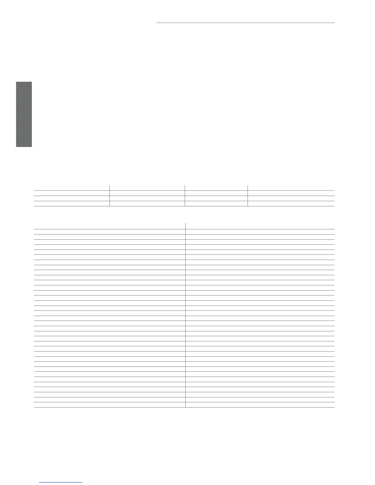
Condenser probe Pre-alarm Alarm Condenser fan outputs selected
Not present Not generated Not generated OFF
Two probes On probe with higher value On probe with higher value On probe with higher value
Error (one of the probes) Generated Generated ON
Tab. 6.h
Function active Function with condenser fan control
Normal direct or reverse-cycle control Normal operation
Remote off, from supervisor or keypad Condenser outputs deactivated, condenser pre-alarm and alarm reset
Defrost Normal operation
Continuous cycle Normal operation
Temperature alarm monitoring Normal operation
Evaporator fan control Normal operation
Power on Normal operation
Normally-open or normally-closed alarm output Normal operation
Auxiliary output Normal operation
Light output Normal operation
Second evaporator output Normal operation
Control output for pump down valve Normal operation
Condenser fan control output Normal operation
Second delayed compressor output Normal operation
Auxiliary output with switch off Normal operation
Light output with switch off Normal operation
No function associated with the AUX output Normal operation
Reverse output in control with dead band Normal operation
Second compressor step output Normal operation
Second compressor step output with rotation Normal operation
Door switch with compressor, fan off and light management Normal operation
Door switch with compressor off and light management Normal operation
Curtain switch with set point variation and light management Normal operation
Light sensor and light management Normal operation
Auxiliary output activation switch Normal operation
Door switch with compressor, fan off, no light management Normal operation
Door switch with compressor off, no light management Normal operation
Light activation from keypad or supervisor Normal operation
Auxiliary activation from keypad or supervisor Normal operation
Alarms See table of alarms and signals
Virtual control probe alarm Normal operation
Product probe alarm Normal operation
Defrost probe alarm Normal operation
Condenser probe alarm Condenser output on, condenser pre-alarm and alarm generated.
Antifreeze probe alarm Normal operation
Tab. 6.i