27
ENGLISH
ir33 +030220441 - rel. 2.0 - 01.05.2006
6.9.2 Continuous cycle in progress
When the continuous cycle is running:
• the compressor is always ON;
• the low temperature alarm is deactivated;
• the icon is on steady.
If, during the continuous cycle, the door is opened and one of the digital inputs is set to manage the
opening of the door, the compressor stops and consequently the continuous cycle is temporarily
interrupted.
When the door closes the continuous cycle starts from where it left off, and thus ,in practice, the
continuous cycle duration timer (cc) is put on hold when the door is opened, and starts again when the
door closes.
6.9.3 End of the continuous cycle
The continuous cycle ends in the following ways:
• pressing (MasterCella, powercompact and powercompact small) or
aux
+
def
(ir33, power
and DIN) for more than 5 seconds;
• minimum specifi ed temperature (AL) reached;
• maximum duration of the continuous cycle (cc) reached;
• instrument switched off (OFF) from the keypad or supervisor;
• changeover from Direct operating mode or Direct with defrost to Reverse-cycle mode (heating), by
parameter (r3) or the digital input (A4, A5).
The low temperature alarm is bypassed for a time (c6) from the end of the continuous cycle.
Note: if control with 2 compressor steps is selected (with or without rotation, H1= 12 or 13) the conti-
nuous cycle activates both steps.
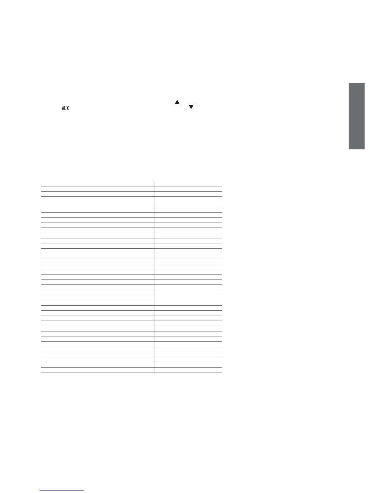
Function active Function with continuous cycle
Normal direct or reverse-cycle control On hold
Remote off, from supervisor or keypad When off, the continuous cycle ends
Defrost If necessary, the request remains during
the continuous cycle
Continuous cycle Normal operation
Temperature alarm monitoring Normal operation
Evaporator fan control Normal operation
Power on Normal operation
Normally-open or normally-closed alarm output Normal operation
Auxiliary output Normal operation
Light output Normal operation
Second evaporator output Normal operation
Control output for pump down valve Normal operation
Condenser fan control output Normal operation
Second delayed compressor output Normal operation
Auxiliary output with switch off Normal operation
Light output with switch off Normal operation
No function associated with the AUX output Normal operation
Reverse output in control with dead band Normal operation
Second compressor step output Activated
Second compressor step output with rotation Activated
Door switch with compressor, fan off and light management Normal operation
Door switch with compressor off and light management Normal operation
Curtain switch with set point variation and light management Normal operation
Light sensor and light management Normal operation
Auxiliary output activation switch Normal operation
Door switch with compressor, fan off, no light management Normal operation
Door switch with compressor off, no light management Normal operation
Light activation from keypad or supervisor Normal operation
Auxiliary activation from keypad or supervisor Normal operation
Alarms See table of alarms and signals
Virtual control probe alarm Normal operation
Product probe alarm Normal operation
Defrost probe alarm Normal operation
Condenser probe alarm Normal operation
Antifreeze probe alarm Normal operation
Tab. 6.g