56
ENGLISH
ir33 +030220441 - rel. 2.0 - 01.05.2006
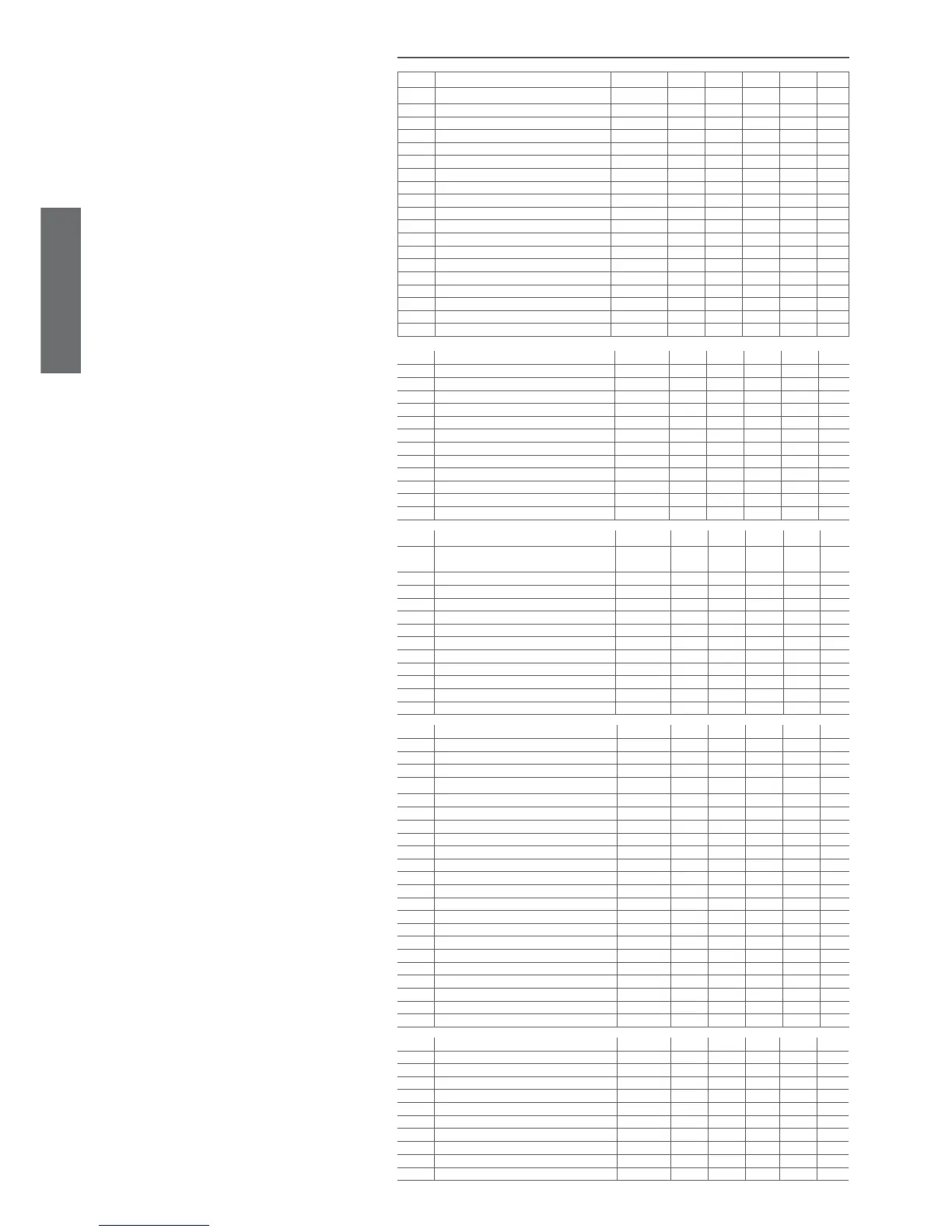
7.10 Summary table of operating parameters
Code Parameter MSYF ** UOM Type Min Max Def.
Pw Password MSYF - C 0 200 22
/2 Measurement stability MSYF - C 1 15 4
/3 Probe display response MSYF - C 0 15 0
/4 Virtual probe MSYF - C 0 100 0
/5 Select °C or °F MSYF fl ag C 0 1 0
/6 Decimal point MSYF fl ag C 0 1 0
/tI Display on internal terminal MSYF - C 1 7 1
/tE Display on external terminal MSYF - C 0 6 0
/P Select type of probe MSYF - C 0 2 0
/A2 Confi guration of probe 2 M-YF - C 0 3 2
-S-- - C 0 3 0
/A3 Confi guration of probe 3 MSYF - C 0 3 0
/A4 Confi guration of probe 4 MSYF - C 0 3 0
/A5 Confi guration of probe 5 MSYF - C 0 3 0
/c1 Calibration of probe 1 MSYF °C/°F C -20 20 0.0
/c2 Calibration of probe 2 MSYF °C/°F C -20 20 0.0
/c3 Calibration of probe 3 MSYF °C/°F C -20 20 0.0
/c4 Calibration of probe 4 MSYF °C/°F C -20 20 0.0
/c5 Calibration of probe 5 MSYF °C/°F C -20 20 0.0
Code Parameter MSYF ** UOM Type Min Max Def.
St Temperature set point MSYF °C/°F F r2 r1 0.0
rd Control delta -SYF °C/°F F 20 0.1 2.0
rn Dead band -SYF °C/°F C 60 0.0 4.0
rr Reverse differential for control with dead band -SYF °C/°F C 20 0.1 2.0
r1 Minimum set point allowed MSYF °C/°F C r2 -50 -50
r2 Maximum set point allowed MSYF °C/°F C 200 r1 60
r3 Operating mode -SYF fl ag C 2 0 0
r4 Automatic night-time set point variation MSYF °C/°F C 20 -20 3.0
r5 Enable temperature monitoring MSYF fl ag C 1 0 0
rt Temperature monitoring interval MSYF hours F 999 0 -
rH Maximum temperature read MSYF °C/°F F - - -
rL Minimum temperature read MSYF °C/°F F - -
Code Parameter MSYF ** UOM Type Min Max Def.
c0 Compressor, fan and AUX start delay on
power up in dead zone
-SYF min C 0 15 0
c1 Minimum time between successive starts -SYF min C 0 15 0
c2 Minimum compressor OFF time -SYF min C 0 15 0
c3 Minimum compressor ON time -SYF min C 0 15 0
c4 Duty setting -SYF min C 0 100 0
cc Continuous cycle duration -SYF hours C 0 15 0
c6 Alarm bypass after continuous cycle -SYF hours C 0 15 2
c7 Maximum pump down time -SYF s C 0 900 0
c8 Comp. start delay after open PD valve -SYF s C 0 60 5
c9 Enable autostart function in PD -SYF fl ag C 0 1 0
c10 Select pump down by time or pressure -SYF fl ag C 0 1 0
c11 Second compressor delay -SYF s C 0 250 4
Code Parameter MSYF ** UOM Type Min Max Def.
d0 Type of defrost -SYF fl ag C 0 4 0
dI Interval between defrosts -SYF hours F 0 250 8
dt1 End defrost temperature, evaporator -SYF °C/°F F -50 200 4.0
dt2 End defrost temperature, aux. evap. -SYF °C/°F F -50 200 4.0
dP1 Maximum defrost duration, evaporator -SYF min F 1 250 30
dP2 Maximum defrost duration, aux evap. -SYF min F 1 250 30
d3 Defrost start delay -SYF Min C 0 250 0
d4 Enable defrost on start-up -SYF fl ag C 0 1 0
d5 Defrost delay on start-up -SYF min C 0 250 0
d6 Display on hold during defrost -SYF - C 0 2 1
dd Dripping time after defrost -SYF min F 0 15 2
d8 Alarm bypass after door open -SYF hours F 0 15 1
d8d Alarm bypass after defrost -SYF hrs/min C 0 250 0
d9 Defrost priority over compressor protectors -SYF fl ag C 0 1 0
d/1 Display of defrost probe 1 MSYF °C/°F F - - -
d/2 Display of defrost probe 2 MSYF °C/°F F - - -
dC Time base for defrost -SYF fl ag C 0 1 0
d10 Compressor running time -SYF hours C 0 250 0
d11 Running time temperature threshold -SYF °C/°F C -20 20 1.0
d12 Advanced defrost -SYF - C 0 3 0
dn Nominal defrost duration -SYF - C 1 100 65
dH Proportional factor, variation in dI -SYF - C 0 100 50
Code Parameter MSYF ** UOM Type Min Max Def.
A0 Alarm and fan differential MSYF °C/°F C 0.1 20 2.0
A1 Type of threshold AL and AH MSYF fl ag C 0 1 0
AL Low temperature alarm threshold MSYF °C/°F F -50 200 0.0
AH High temperature alarm threshold MSYF °C/°F F -50 200 0.0
Ad Low and high temperature signal delay MSYF min F 0 250 120
A4 Digital input 1 confi guration -SYF - C 0 14 0
M--- - C 0 14 3
A5 Digital input 2 confi guration MSYF - C 0 14 0
A6 Stop compressor from external alarm -SYF min C 0 100 0
A7 Enable alarms Ed1 and Ed2 -SYF min C 0 250 0