51
ON ventole
prima accensione
“F4” + “F5”
“F4” 0.2
temp. condensatore
Fig. 7.p
ENGLISH
ir33 +030220441 - rel. 2.0 - 01.05.2006
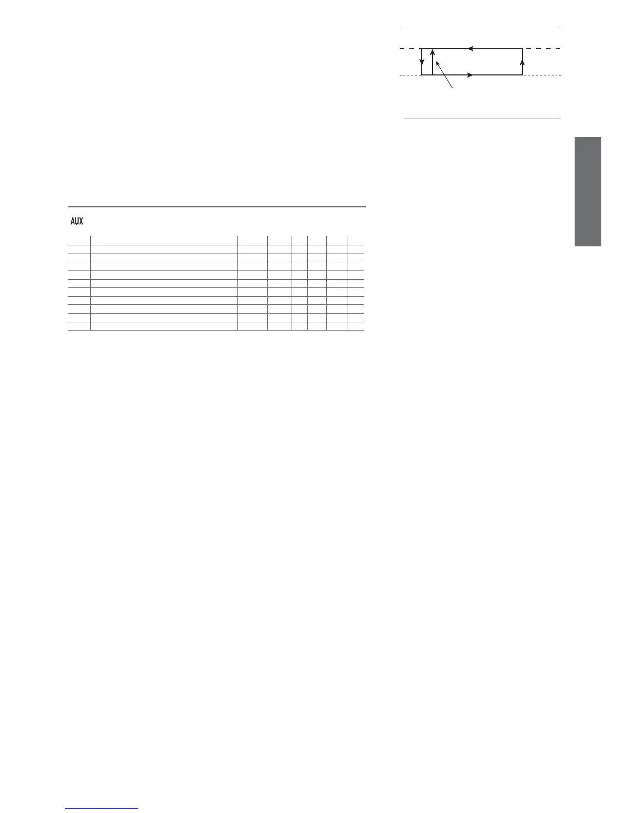
F4: Condenser fan stop temperature
This is used to select the temperature at which the condenser fans should be switched OFF. If setting the
auxiliary relay as the condenser fan output (see parameter H1), this will enable adjustments according to
the diagram in Figure 7.p:
When the compressor is fi rst started, the fans are switched ON at F4 + 0.2 degrees to compensate for
rapid temperature increases that are not easy for the probe to follow.
After this, control is performed normally, i.e.:
• on: F4 + F5
• off: F4.
In the event of condenser probe errors, the condenser fan output, if selected, is activated.
Important: If no condenser probe is selected, the condenser fan output, if selected, is disabled.
Default: F4=40.0 degrees.
F5: Condenser fan start differential
This is the differential used to control the condenser fans.
Default: F5=5.0.
7.7 General confi guration parameters
Code Parameter MSYF ** UOM Tipo Min Max Def.
H0 Serial address MSYF - C 0 207 1
H1 Function of relay 4 MSYF fl ag C 0 13 1
H2 Disable keypad/IR MSYF fl ag C 1 6 1
H3 Remote control enabling code MSYF - C 0 255 0
H4 Disable buzzer MSYF fl ag C 0 1 0
H5 Function of relay 5 - C 0 10 3
H6 Lock keypad MSYF - C 0 255 0
H8 Select activation of output with time band MSYF fl ag C 0 1 0
H9 Enable set point variation with time band MSYF fl ag C 0 1 0
Hdh Anti-sweat heater offset MSYF °C/°F C -50 200 0.0
Tab. 7.m
Note:
- par. H5 refers to the instruments with 5 relays (ir33DIN, powercompact and MasterCella);
- parameters HPr, HrL, HrA, HsA and In are masked and consequently only visible using the
programming kit (IROPZPRG00).
H0: Serial address
This is used to assign to the instrument an address it responds to when connected to a supervisory or
telemaintenance system. Default: H0=1.
H1: Operating mode: logic of output AUX1
Establishes whether the fourth relay is used as an auxiliary output.
The following functions can be associated:
H1=0 - alarm output normally energised. The relay is de-energised when an alarm occurs. The AUX
output in “alarm” mode can be set to operate either with the relay energised or de-energised. The latter
mode ensures maximum safety, because the alarm is also activated in the event of power failures or
disconnection of the cables.
H1=1 - alarm output normally de-energised: the relay is energised when an alarm occurs.
H1=2 - auxiliary output: the actuator connected can be switched ON/OFF using the AUX button.
Switching the actuator ON/OFF is signalled by the icon on the display.
H1=3 - light output: the light on the unit can be switched on/off when the door is opened, if the door
switch is enabled (see parameter A4). In this case, the light is switched off when the door is closed,
unless previously switched off from the keypad. Switching the light on/off is signalled by the icon on the
display.
H1=4 - auxiliary evaporator defrost output: a heater or reversing valve can be controlled to perform an
electric heater defrost or hot gas defrost on the auxiliary evaporator.
H1=5 - pump down valve output: the activation and the deactivation of the pump down valve can be
controlled.
H1=6 - condenser fan output: if the high condenser temperature alarm is activated (see Ac), the output
can be used to control the condenser fans.
H1=7 - delayed compressor output: the output is activated a few seconds after the compressor starts (the
delay is established by parameter c11, deactivation of the compressor output corresponds to immediate deac-
tivation of the delayed compressor. If this operating mode is set, it is also active during the compressor pump
down and autostart phases, if selected with the appropriate parameters.
H1=8 - auxiliary output with deactivation when OFF: in the off status, the auxiliary output cannot be
activated. When starting again, the auxiliary output returns to the previous status.
H1=9 - light output with deactivation when OFF: in the off status, the light cannot be activated. When
starting again, the light returns to the previous status.
H1=10 - no function associated with the output. In this case, the logical output AUX1 is not used for any
function. If logical outputs AUX1 and AUX2 are associated with the same relay, this setting means the
relay in question will only be associated with AUX2. Vice-versa, using this setting for AUX2, the relay will
only be associated with AUX1. This possibility is useful when there is just one auxiliary relay, and it needs
to be used alternatively as a light relay, associated with the light button and icon, or as an AUX relay,
associated with the AUX button and icon.