21
ENGLISH
ir33 +030220441 - rel. 2.0 - 01.05.2006
6.4 Auxiliary output management
The auxiliary output can be controlled by a number of sources: button, supervisor, digital input, and time
band. The AUX is switched on and off in the following events:
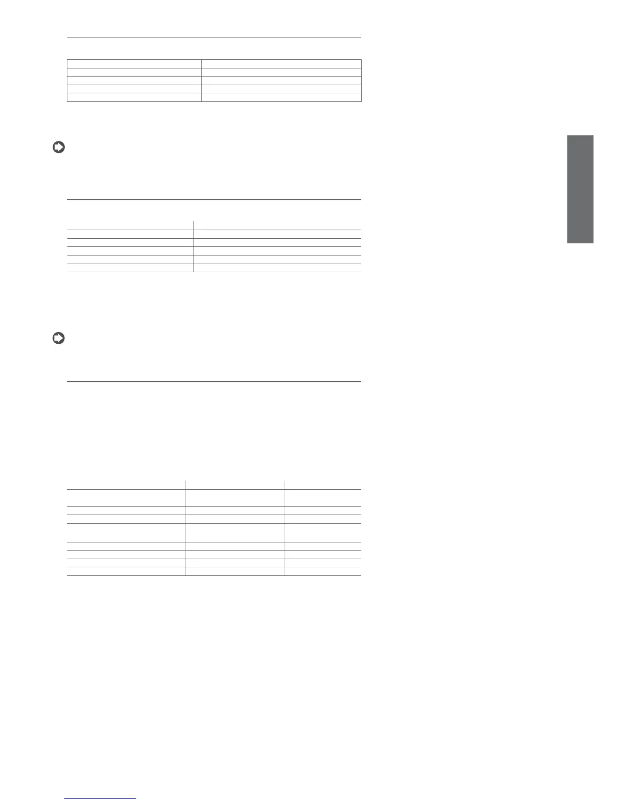
Aux Action
Button pressing the button
Supervisor variation in value from the supervisor
Digital input change in the status of the contact (opening/closing)
Time band according to day, hour, minutes for switching on/off
Tab. 6.e
Therefore, if the digital inputs are stable, the AUX output can always be activated and de-activated from the
keypad or the supervisor. The timed light or AUX on/off events (parameters tON and tOFF, depending on
parameter H8) are also active when the unit is off.
Note: the anti-sweat heater function, when the control is powered up or switched on, keeps the auxiliary
output off until the control temperature is below the set value. The AUX output is activated when the
event occurs.
6.5 Light management
The light can be controlled by a number of sources: button, supervisor, door switch and curtain switch.
The light is switched on and off in the following events:
Light Action
Button pressing the button
Supervisor variation in value from the supervisor
Door switch change in the status of the contact (opening/closing)
Curtain switch change in the status of the contact (opening/closing)
Light sensor on detecting light or darkness
Tab. 6.f
When the digital inputs (selected as door or curtain switches) are stable, the light can always be switched
on or off from the keypad or the supervisor. The door switch features two different algorithms for
switching the light on/off:
• the status of the light is not affected, and acts only on the compressor and fans;
• timed light or AUX on/off events (depending on parameter H8) are also active when the unit is off.
Note: the anti-sweat heater function, when the control is powered up or switched on, keeps the light
output off until the control temperature is below the set value. The light output is activated when the
event occurs.
6.6 Defrost
The parameter dC establishes the measurement unit for the times set by the parameters dI (defrost
interval) and dP1, dP2 (maximum defrost duration). If the auxiliary relay is selected as the auxiliary
evaporator defrost output (H1), the defrost is performed at the same time on both evaporators.
The parameter d/1 displays the defrost probe set for the main evaporator (the fi rst probe assigned as
a defrost probe); while parameter d/2 displays the defrost probe set for the secondary evaporator (the
second probe assigned as a defrost probe). If no probes have been assigned to the defrost function, the
defrost will end by timeout, after the periods dt1 and dt2.
6.6.1 Defrost events
The following events activate the defrost function:
Event Implementation Condition
Interval between defrosts dI expired Depending on enabling status At the expiry of the interval
Expiry of RTC trigger Depending on enabling status -------
Compressor running time Depending on enabling status When the defrost starts
Interval between defrosts dI expired with
skip defrost algorithm
Depending on enabling status At the expiry of the interval
At start-up Depending on enabling status At start-up + d5
Digital input Depending on enabling status When the defrost starts
Supervisor Always --------
Keypad Always --------
Tab. 6.g
Implementation of defrost depending on enabling status:
If a digital input is confi gured to enable the defrost, the defrost is performed when such input is in the
enabling status, otherwise it stays pending.
Important: the defrost started from the keypad or by the supervisor is always performed, even when
there is a delayed defrost request from external digital input or if there is a defrost enabling input (in
non-enabled or delayed status). If parameter r3 is set to 1 (Direct) or 2 (Reverse), the defrost is never
performed.
6.6.2 Defrost request status
This status exists when one of the events that activates the defrost is present, but defrost cannot be
started and, therefore, is put on hold for the following reasons:
• compressor and fans start-up delay (c0), as these delay the activation of the compressor;
• compressor protection times (c1, c2, c3), as these delay the activation of the compressor;
• low pressure alarm (only with hot gas defrost), as this delays the activation of the compressor;
• continuous cycle running;
• pump down procedure running, as this delays the activation of the compressor;
• defrost delay at start-up (d5);
• defrost delay from digital input confi gured as defrost start or enable (d5);
• enable defrost (A4, A5);