34
ENGLISH
ir33 +030220441 - rel. 2.0 - 01.05.2006
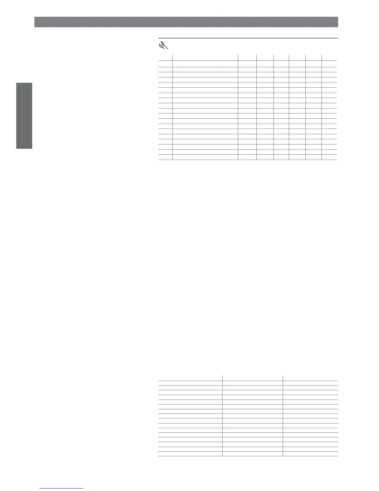
7.1 Temperature probe management parameters
Code Parameter MSYF ** UOM Type Min Max Def.
Pw Password MSYF - C 0 200 22
/2 Measurement stability MSYF - C 1 15 4
/3 Probe display response MSYF - C 0 15 0
/4 Virtual probe MSYF - C 0 100 0
/5 Select °C or °F MSYF fl ag C 0 1 0
/6 Decimal point MSYF fl ag C 0 1 0
/tI Display on internal terminal MSYF - C 1 7 1
/tE Display on external terminal MSYF - C 0 6 0
/P Select type of probe MSYF - C 0 2 0
/A2 Confi guration of probe 2 M-YF - C 0 3 2
-S-- - C 0 3 0
/A3 Confi guration of probe 3 MSYF - C 0 3 0
/A4 Confi guration of probe 4 MSYF - C 0 3 0
/A5 Confi guration of probe 5 MSYF - C 0 3 0
/c1 Calibration of probe 1 MSYF °C/°F C -20 20 0.0
/c2 Calibration of probe 2 MSYF °C/°F C -20 20 0.0
/c3 Calibration of probe 3 MSYF °C/°F C -20 20 0.0
/c4 Calibration of probe 4 MSYF °C/°F C -20 20 0.0
/c5 Calibration of probe 5 MSYF °C/°F C -20 20 0.0
Tab. 7.a
Note: par. /A5 and /c5 refer to instruments with 5 relays (ir33DIN, powercompact and MasterCella).
‘/2’: Measurement stability
Defi nes the coeffi cient used to stabilise the temperature reading. Low values assigned to this parameter
allow a prompt response of the sensor to temperature variations, but the reading becomes more sensitive
to disturbance. High values slow down the response, but guarantee greater immunity to disturbance, that
is, a more stable and more precise reading. The parameter acts on the temperature readings, fi ltering the
minimum variations, and at the same time considers the average of the readings. Default: ‘/2’=4.
/3: Probe display response
This parameter is used to set the update rate for the temperature display. The temperature shown on the di-
splay tends to follow rapid deviations away from the set point very slowly, and vice-versa, moves very quickly in
the event where the temperature displayed is nearing the set point. If the control temperature exceeds the high
or low temperature thresholds (and an AL or AH alarm is activated), or if the maximum number of fi ltering
steps (255) is exceeded (see the Timeout column in Table 7.b), the fi ltering would immediately be bypassed
and the temperature displayed would be the temperature effectively measured, until all the alarms are reset.
The parameter only affects the temperature displayed, and not the temperature used for the control functions.
Important:
• the control temperature actually measured differs from the value displayed, and therefore the outputs
may not be activated with reference to the latter temperature value.
• if the probe displayed is a product probe, with temperature values higher than the set point, the probe
display rate algorithm will be faster for decreases in the temperature and slower for increases;
• if the probe displayed is an evaporator or condenser probe, the display rate algorithm always refers to
the set point and thus may have specifi c effects (fast when the evap. probe reading increases and slow
when it decreases; fast when the condenser probe reading decreases and slow when it increases);
• the parameter /3 acts on the temperature displayed by the instrument, if /tE=0 (no probe displayed by
the repeater display); if the repeater display is confi gured (/tE <> 0), the parameter /3 will act on the
temperature displayed by the repeater.
Example: in the case of “bottle coolers”, typically used in supermarkets, when the doors are opened
frequently, due to the greater thermal inertia of the liquids compared to the air (and the fact that the
probe is positioned in the air and not directly on the products), the instrument measures a tempera-
ture that is higher than effective temperature of the soft drinks, thus displaying a quite “unrealistic”
temperature. Setting the parameter /3 to a value other than 0, any abrupt variations in temperature
are “fi ltered” on the display, showing a temperature trend that is “closer” to the actual trend of the
product temperature. The following table shows the possible values of ‘/3’ and the corresponding
display delayed update values (Tdel).
Value of par. /3 Display delay (Tdel) Timeout
0 Disabled 0
1 5 s 21 min
2 10 s 42 min
3 15 s 64 min
4 20 s 85 min
5 25 s 106 min
6 30 s 127 min
7 40 s 170 min
8 50 s 212 min
9 60 s 255 min
10 75 s 319 min
11 90 s 382 min
12 105 s 446 min
13 120 s 510 min
14 150 s 637 min
15 180 s 765 min
Tab. 7.b
Default: ‘/3’=0 => Function disabled.
7. DESCRIPTION OF THE OPERATING PARAMETERS