23
ENGLISH
ir33 +030220441 - rel. 2.0 - 01.05.2006
6.6.7 Dripping
The dripping time is set by parameter dd, when the compressor is OFF and the fans are OFF. At the end
of dripping time, the post-dripping phase starts with the fans OFF (Fd):
• the compressor restarts normal operation;
• the fans remain off.
If the post-dripping time with fans OFF is set to zero, normal control is resumed directly.
Post-dripping (fans OFF)
The post-dripping time with fans OFF is set by parameter Fd. At the end of the post-dripping time with
the fans OFF, normal control resumes.
Notes on the defrost function
• If defrost with RTC is selected, the parameter dI has no effect. In any case, the dI timer is updated and
the parameter becomes valid on all days only in the event of RTC alarms. The parameter dI should
therefore be set for safety reasons.
• The timer used to determine the defrost interval dI is updated cyclically when reaching the end of the
interval, thus enabling cyclical defrosts. The timer is also updated when the unit is OFF. If the timer dI
expires when the unit is OFF, a defrost is performed when the unit is started. If an “RTC” or manual
defrost is run from the keypad or the supervisor, the timer linked to dI is not reset at the start of the
defrost. Consequently, at the end of defrost, the dI timer may expire, and another defrost may be
performed. If a defrost is run from the digital input, with the compressor running time algorithm, or
from the supervisor in Slave controllers, the timer dI is reset when the defrost request is generated. In
this way, the defrost interval is a timeout for the generation of the defrost requests (used, for example,
when the external timer is not working correctly). If defrost on start-up (d4) has been selected, and a
defrost on start-up delay (d5) has been set, the timer dI must be set to the end of the defrost delay on
start-up. For units programmed in the same way, and with the same value of ‘dI’ and different values
of ‘d5’, this enables the defrosts at start-up to be distributed through time, and the time staggering
of the defrosts to be maintained for the subsequent events too. If control with 2 compressor steps is
selected (with or without rotation, H1 = 12 or 13) the hot gas defrost requires the activation of the 2
steps, while the heater defrost deactivates the steps.
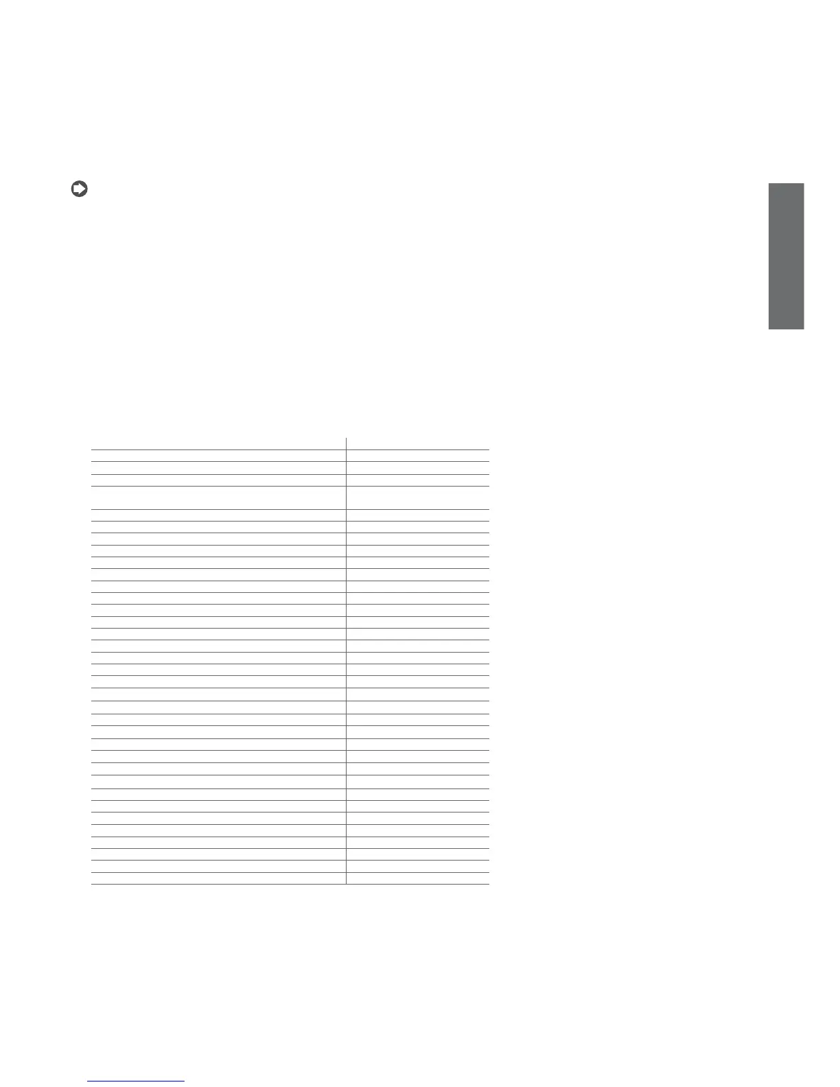
Function active Function with defrost
Normal direct or reverse-cycle control On hold
Remote off, from supervisor or keypad When off the defrost is terminated
Defrost Normal operation
Continuous cycle If required, the request remains during
the defrost
Temperature alarm monitoring Normal operation
Evaporator fan control Normal operation
Power on Normal operation
Normally-open or normally-closed alarm output Normal operation
Auxiliary output Normal operation
Light output Normal operation
Second evaporator output Normal operation
Control output for pump down valve Normal operation
Condenser fan control output Normal operation
Second delayed compressor output Normal operation
Auxiliary output with switch off Normal operation
Light output with switch off Normal operation
No function associated with the AUX output Normal operation
Reverse output in control with dead band Normal operation
Second compressor step output On hold
Second compressor step output with rotation On hold
Door switch with compressor, fan off and light management Normal operation
Door switch with compressor off and light management Normal operation
Curtain switch with set point variation and light management Normal operation
Light sensor and light management Normal operation
Auxiliary output activation switch Normal operation
Door switch with compressor, fan off, no light management Normal operation
Door switch with compressor off, no light management Normal operation
Light activation from keypad or supervisor Normal operation
Auxiliary activation from keypad or supervisor Normal operation
Alarms See table of alarms and signals
Virtual control probe alarm Normal operation
Product probe alarm Normal operation
Defrost probe alarm Defrost ended due to timeout.
Condenser probe alarm Normal operation
Antifreeze probe alarm Normal operation
Tab. 6.h