45
d5
d
dP
t
d5
sbrinamento
sbrinamento
sbrinamento
tempo
unità 1
unità 2
unità 3
richiesta di sbrinamento
Fig. 7.l
ENGLISH
ir33 +030220441 - rel. 2.0 - 01.05.2006
Note:
• if more than one digital input is confi gured as the immediate alarm, the alarm will be generated when
at least one of the inputs is open.
• if control with two compressor steps is selected (with or without rotation, H1, H5 = 12 or 13) the
immediate external alarm acts on both steps.
A4=2 Delayed external alarm
The delayed external alarm is equivalent to the immediate external alarm (A4=1), except that this alarm
is signalled after the time A7 from when it is detected (‘dA’ signal). This confi guration is especially useful
for managing the low pressure alarm. In fact, when starting for the fi rst time, the unit often detects a low
pressure alarm due to the environmental conditions rather than the malfunctioning of the unit.
Setting a delay for the alarm will avoid false signals. In fact, by suitably calculating the delay, if the low
pressure is due to environmental conditions (low temperature), the alarm will be automatically reset
before the delay has elapsed.
Note:
• if ‘A7’=0, the activation of the alarm does not cause the compressor to operate according to the values
assigned to the parameter ‘A6’ (stop compressor from external alarm); on the other hand, the ‘dA’
signal is displayed, the icon fl ashes, the buzzer and the alarm relay (if selected) are activated;
the delayed external alarm is thus signal-only.
• both the immediate and delayed external alarm have automatic reset;
• if more than one digital input is confi gured as the delayed alarm, the alarm will be generated when at
least one of the inputs is open;
• if control with two compressor steps is selected (with or without rotation, H1, H5 = 12 or 13) the
delayed external alarm acts on both steps.
A4 =3 The meaning varies according to the model used
Version ir33M = probe selection
This is used to exploit the digital input in order to show, on the display, the probe selected by parameter
/tI or the fi rst enabled probe (see parameters /A2, /A3, /A4, /A5). In practice, if the contact is open, the
probe selected by parameter /tl is shown, whereas, if the contact is closed, the fi rst enabled probe is
shown.
For all other models = Defrost enabling
An external contact can be connected to the multifunction input to enable or inhibit the defrost.
• Contact open: the defrost is inhibited. Contact closed: the defrost is enabled.
• Contact closed without request from the controller: the defrost is not performed.
• Contact closed and defrost in progress: when the digital input is opened, the defrost is immediately
stopped and the unit restarts normal operation (without performing the dripping or post-dripping pha-
ses). The LED starts fl ashing to indicate that the defrost request is pending, awaiting the next enabling
signal (closing of the contact), when the defrost will be performed completely..
Suggestion: this function is useful in the following situations, for example:
- multiplexed showcases with hot gas defrost. In these systems, defrosts must be performed by “islands”,
and therefore, at any one time, some islands are enabled to be defrosted, while others are disabled;
- to prevent defrosts on the units accessible by the public during opening times. Any defrost request
arriving when the contact is open will remain pending until the contact closes.
A4 = 4 Start defrost from external contact
This function used to start the defrost from an external contact.
If dI=0 and no defrost enabling signal related to the clock is set, the defrost can only be performed on
start-up, from the digital input, by the supervisor and from the keypad. This function is useful to run real
time defrosts. To perform the defrosts, connect a cyclical, mechanical or electronic timer to the digital
input: When the contact on the timer closes, the defrost request is sent.
As seen in the description of parameter d5, a series of units can be connected to the same timer.
Important warning for versions operating on 12Vac and 12-24Vac
When connecting a series of units to the same timer, the best solution is to insulate all the contacts
galvanically, inserting an intermediate relay for each contact. Setting a different value for d5 on each unit
will avoid simultaneous defrosts.
Note: if more than one digital input is confi gured to enable the defrost, the defrost will be disabled
when at least one of the inputs is closed.
A4 = 5 Door switch with compressor and fan stop
Setting A4=5 manages the cold room door switch. The behaviour of the door switch depends on
whether the door is opened with the light OFF or light ON. The need to differentiate the two operating
modes is mainly designed for controlling display cases and cold rooms.
Case 1 - door opened with light OFF:
If the door is opened with the light OFF:
• the compressor and evaporator fans are switched off (to stop the fans only, set parameter A4=9);
• in the models fi tted with an auxiliary relay programmed as the light output, the light is switched on;
• the reading displayed and the icon fl ash;
• the temperature alarms are disabled.
If the door remains open for longer than time d8, the controller restarts normal operation:
• compressor and fan ON, if requested;
• light ON (the auxiliary relay is selected as the light);
• the buzzer and the alarm relay are activated;
• the temperature alarms are enabled;
• the reading fl ashes.
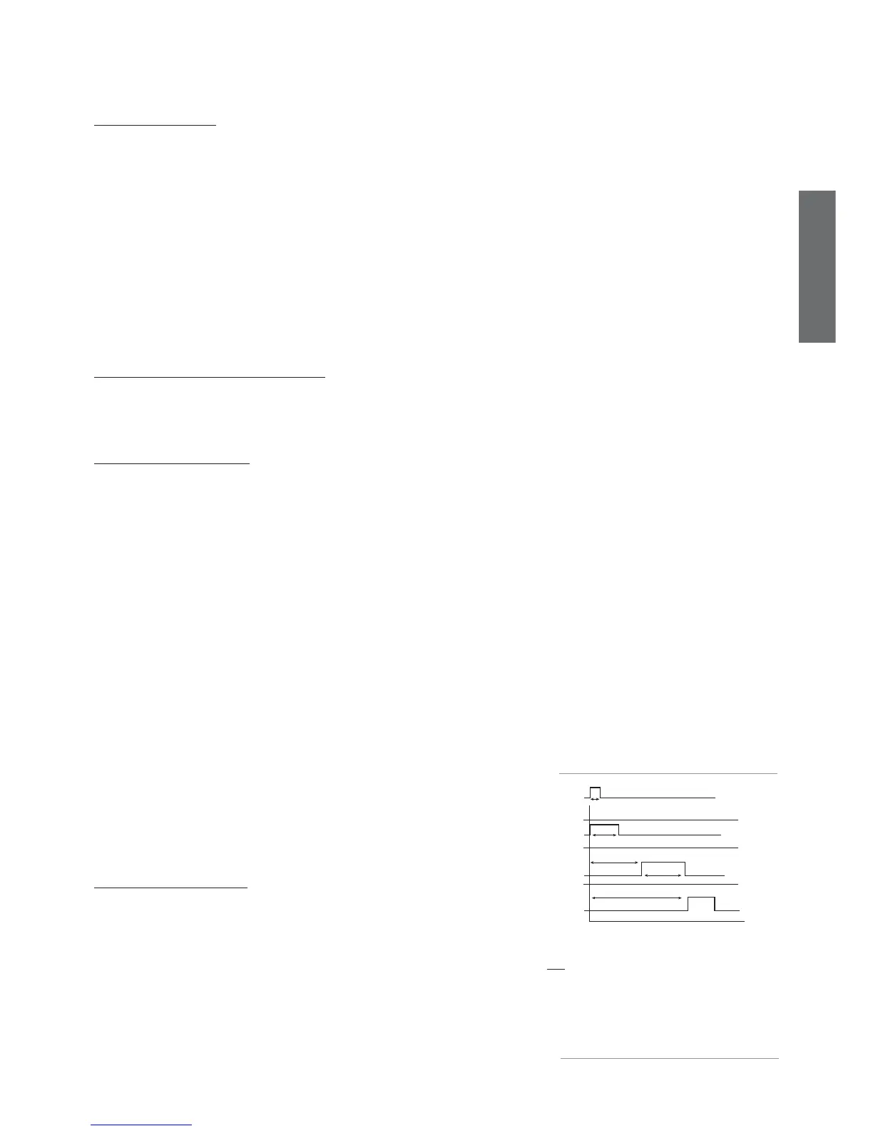
Key:
t= impulse from the timer to start the defrost:
the minimum duration must be 0.5 s.
dP (1)= maximum defrost duration on unit 1.
dP(2)= defrost delay from external contact for unit 2,
higher than dP(1) to prevent overlapping
defrosts.
Same for d5(3) and dP(3).