— 12 —
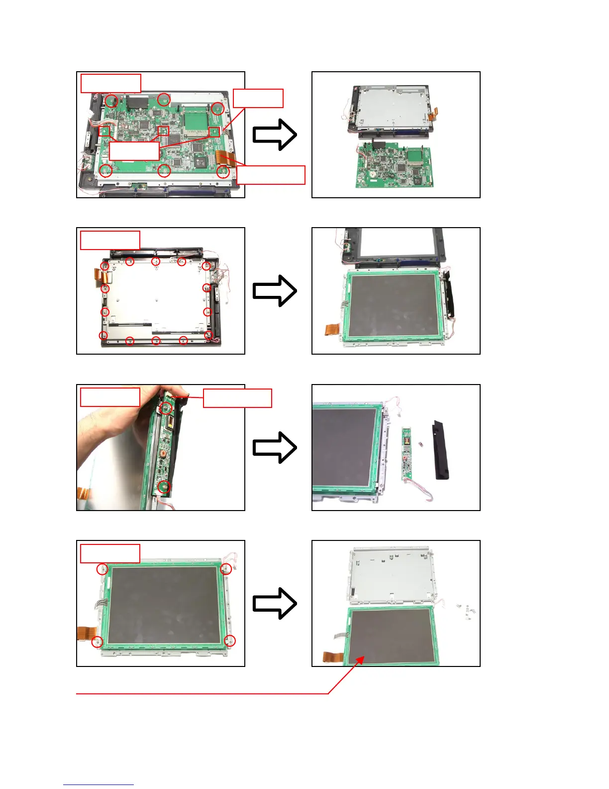
16. Remove six screws, one connector, one FPC, three bosses, and then remove the main PCB.
FPC
Connectors
boss
Screw
×
6
17. Remove 14 screws and then the LCD unit.
18. Remove two screws, one connector and the inverter PCB.
19. Remove four screws and the LCD.
Screw
×
14
Screw
×
2
Connectors
Screw
×
4
The touch panel is fixed by double-sided tape.
 Loading...