Assembly and operating instructions
CENTAX-L
016L-00050…00090-FS10
CENTA Antriebe Kirschey GmbH 4 / 46
Index of illustrations
Fig. 5-1 Axial misalignment ........................................................................ 13
Fig. 5-2 Radial misalignment ...................................................................... 14
Fig. 5-3 Angular misalignment .................................................................... 16
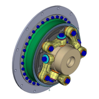
Fig. 6-1 Example: 016L-00064-FS10 ........................................................... 20
Fig. 6-2 Example: 016L-00064-FS10 ........................................................... 20
Fig. 6-3 Mounting the hub with cylindrical bore and keyway ........................... 22
Fig. 6-4 Mounting the hub with conical oil interference fit .............................. 24
Fig. 6-5 Positioning the link flange assembly (1) ........................................... 27
Fig. 6-6 Mounting the link flange assembly with/without sheet (5) .................. 28
Fig. 6-7 Mounting the adapter (8) to the flywheel ......................................... 30
Fig. 6-8 Mounting the link flange assembly to the adapter (8) ........................ 31
Fig. 6-9 Mounting the links ("ccw" counterclockwise rotation) ......................... 34
Fig. 6-10 Mounting the links ("cw" clockwise rotation) ................................... 34
Index of tables
Table 2-1 Shape and size of ventilation holes ................................................ 8
Table 5-1 Permissible radial alignment tolerance .......................................... 15
Table 5-2 Permissible angular alignment tolerance ........................................ 17
Table 6-1 Guide to links ............................................................................. 33
Table 7-1 Troubleshooting table ................................................................. 37