CENTRALINE I/O MODULES – INSTALLATION & COMMISSIONING INSTRUCTIONS
17 EN1Z-0973GE51 R0119
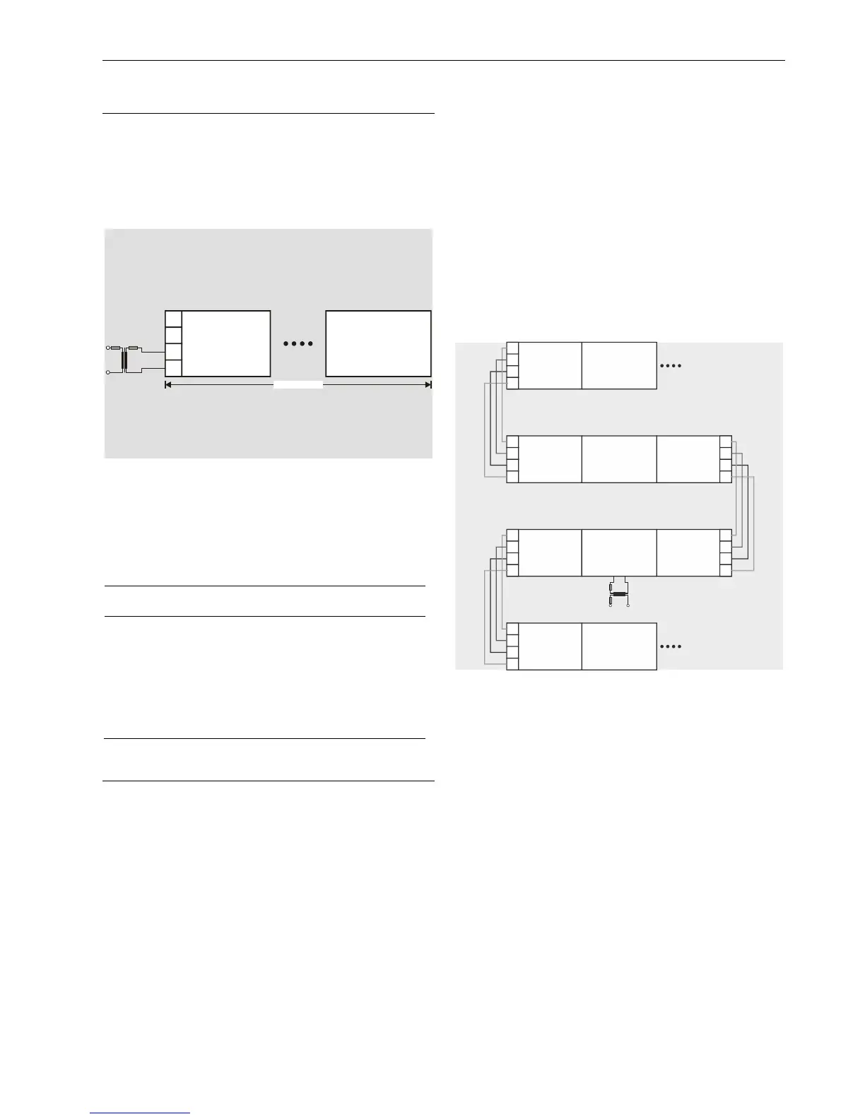
Connecting Power Supply
The CentraLine controller system can be powered by one or
more external transformers.
NOTE: The max. length for the power supply cable from a
transformer is 3 m. This also includes the length of
the modules and the connection cables between
the rails.
I/OI/O
71
72
73
74
MAX. 3 m
TRANS-
FORMER 2
Fig. 18. Wiring the power supply from a transformer
Additional Transformer / DC Power Supply
► Connect the additional transformer / DC power supply in a
second room or cabinet to terminals 73 and 74 or 77 and
78 of a CentraLine I/O module.
NOTICE
Equipment damage!
► Do not use bridge connectors to connect modules
powered by different transformers / DC power supplies.
► When connecting modules powered by different trans-
formers / DC power supplies using cables, be sure to not
connect terminals 73 and 77.
Connecting Single Bus Controller Systems
This section describes how to connect a controller system
which uses Panel Bus I/O modules only or L
ONWORKS Bus
I/O modules only.
Controller and CentraLine I/O Modules on a Single
Rail
► Connect the controller and CentraLine I/O modules using
the bridge connectors (if supported); otherwise, use wire.
This provides power supply and communication connection.
No further wiring is necessary.
Controllers not Supporting Bridge Connectors
► Connect the controller and CentraLine I/O modules which
do not support bridge connectors using wire. See also Fig.
22.
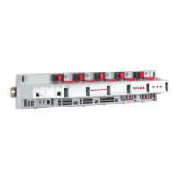
Controller and I/O Modules on Several Rails in a
Single Cabinet
The rails of a controller system are connected in series.
► Connect the rail ends as follows:
– Power supply
via power supply terminals 73, 74 or 77, 78
– Communication
via communication terminals 71, 72 or 75, 76
I/O
I/OI/O
I/O
I/O
I/O
I/O
I/O
I/O
75
75
71
71
71
71
76
76
72
72
72
72
77
77
73
73
73
73
78
78
74
74
74
74
CPU
Fig. 19. Wiring the power supply and the communication
lines to the CentraLine I/O modules
Max. Power Cable Length
The max. length for power supply cable per side is 3 m. This
includes the connection cables between the rails, the lengths
of the modules, and the cable from the transformer.
Panel Bus I/O Modules in Separate Rooms
In this scenario, communication and reference voltage
(24 V0) must be connected between the rooms.
► Connect the last module of room 1 to the first module of
room 2:
– Reference voltage
via power supply terminals 74 or 78
terminals 73 and 77 must not be connected
– Communication
via communication terminals 71, 72 or 75, 76