CENTRALINE I/O MODULES – INSTALLATION & COMMISSIONING INSTRUCTIONS
EN1Z-0973GE51 R0119
36
Relay Output Modules
Types of Relay Output Modules and Terminal Socket
Table 39. CentraLine Relay Output Modules
Type Description Housing
CLIOP824A Panel Bus relay output module Light gray
CLIOPR824A
Panel Bus relay output module
with manual overrides
Light gray
CLIOL824A LONWORKS Bus relay output
module
Dark gray
CLIOLR824A
L
ONWORKS Bus relay output
module with manual overrides
Dark gray
XS824-25
XSU824-25
Terminal socket; can be fitted
with cross connector (incl. in
the delivery)
Light gray
Features
6 relays (changeover contacts), arranged in two blocks
…R824A: 6 manual overrides
Low and line voltage allowed, see WARNING.
21
564
3
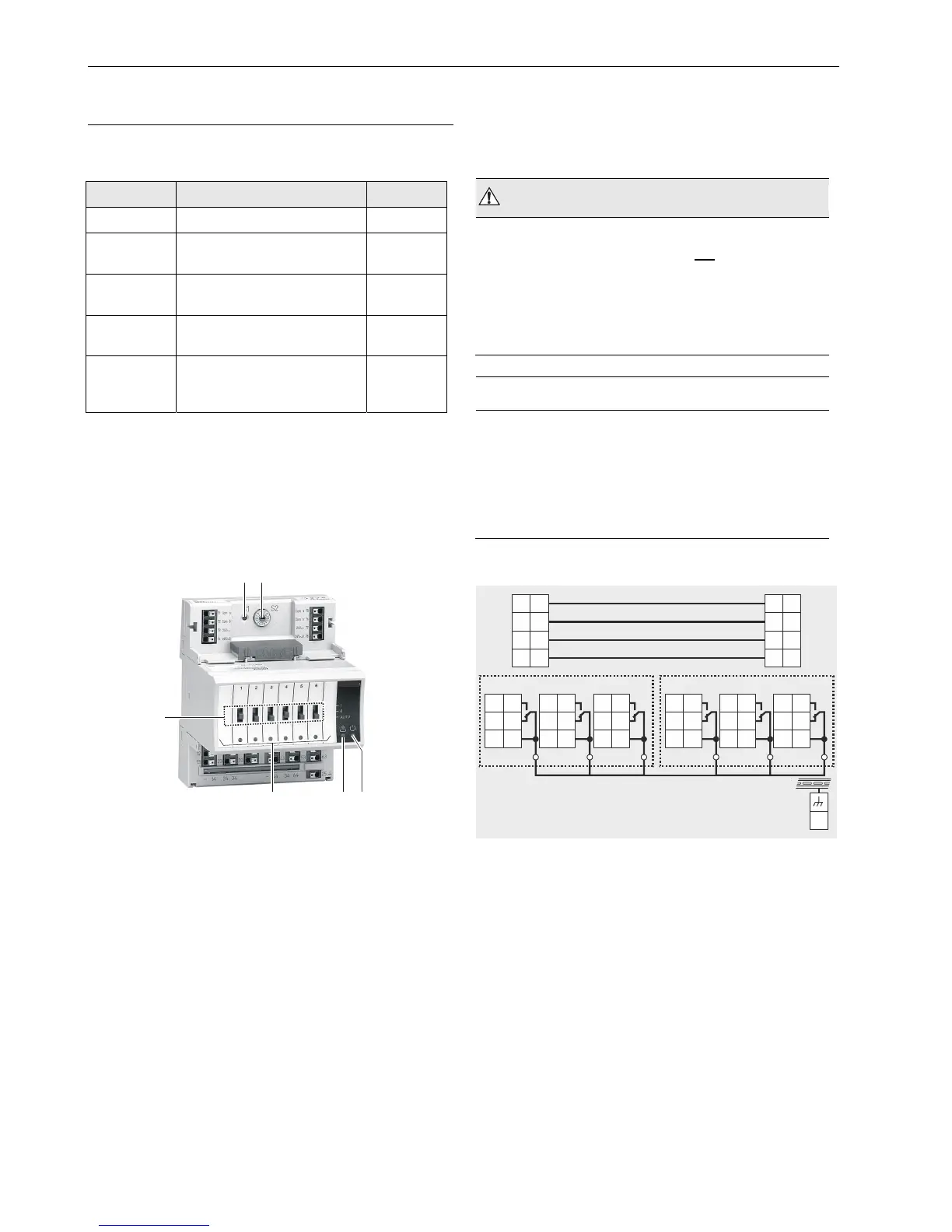
Fig. 45. CLIOP824A Relay Output Module with terminal
socket
Legend
1 Service button S1
2 Hex switch S2
3 Manual overrides
4 Status LEDs
5 Service LED
6 Power LED
Functionality of service LED and power LED: see Table 57 to
Table 59 on page 56 and following.
In the event of communication problems, the relay outputs will
move to the safety positions you have configured using the
engineering tool, see relay output point description in the
CARE – User Guide, 74-5587/EN2B-0182GE51.
WARNING
Risk of electric shock or equipment damage!
Low voltage and line voltage must not be wired within
the same relay block.
► Wire low voltage e.g., to relay block 1 and line voltage to
relay block 2 or vice versa. In this case, a cross
connector must not be used; rather, each relay must be
wired separately.
NOTICE
Risk of malfunction!
Cross connectors may only be used if the same voltage
is used on all relays they connect.
► Do not use a cross connector if different voltages are
used on any of the six relays. In such cases, each relay
must be wired separately.
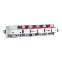
Terminals
REMOVABLE CROSS CONNECTOR (FACTORY-MOUNTED)
NO
NC
COM
11
12
13
NO
NC
COM
21
22
23
31
32
33
NO
NC
COM
41
42
43
NO
NC
COM
51
52
53
NO
NC
COM
61
62
63
NO
NC
COM
25
71
75
72
76
73 77
74
78
COM
A
COM
A
COM
B
COM
B
24
V~
24
V~
24
V~0
24
~0
RELAY BLOCK 1 RELAY BLOCK 2
Fig. 46. Terminal assignment and internal connections