CENTRALINE I/O MODULES – INSTALLATION & COMMISSIONING INSTRUCTIONS
EN1Z-0973GE51 R0119
12
Mounting/Dismounting Modules
WARNING
Risk of electric shock or equipment damage!
► Do not touch any live parts in the cabinet.
► Disconnect the power supply before you start to install
the controller system.
More than one disconnect switch may be required to de-
energize the system.
► Do not reconnect the power supply until you have
completed the installation.
► Unused terminals must be closed (by completely
screwing in the terminal screws), thus preventing the
accidental touching of “live” parts.
NOTE: The terminal socket of each pluggable I/O
module can be mounted and wired before
inserting and locking the corresponding electronic
module.
PRESS
PRESS
PRESS
PRESS
1
2
3
Honeywell
AUTO
0
!
AAA
100
S1 S2
2
1
0
F
E
D
C
B
9
8
7
6
5
4
3
A
71 COM a
72 COM b
73 24V
~
74 24V 0
~
21
22
23
14 4424 5434 64 25
13
12
11
31
32
33
41
42
43
51
52
53
61
62
61
62
6363
12
3
4
5678
Honeywell
AUTO
0
!
AAAAAAAA
100
S1 S2
2
1
0
F
E
D
C
B
9
8
7
6
5
4
3
A
21
9
GND GND
AI/AOV
AUX
10 11 12 13 14 15 16 17 18 25 26
22 1 2
3
4
5678
12
3
4
56
Honeywell
--1
--0
--AUTO
!
S1 S2
2
1
0
F
E
D
C
B
9
8
7
6
5
4
3
A
21
22
23
14 4424 5 434 64 25
13
12
11
31
32
33
41
42
43
51
52
53
61
62
61
62
6363
12
3
45678
Honeywell
!
21
9
GND GND
AI/AOV
AUX
10 11 12 13 14 15 16 17 18 25 26
22 1 2
3
4
5678
GND
BI
13 14 15 16 17 18 19 20 21 22 23 24 25 26
12
3
4
5678910
11 12
1 2
3
4 5 6 7 8 9 10 11 12
Honeywell
!
S1 S2
2
1
0
F
E
D
C
B
9
8
7
6
5
4
3
A
71 COM a
72 COM b
73 24V
~
74 24V 0
~
PRESS
PRESS
1:ABCDFERTAQWESDERT1
2:ABCDFERTAQWESDERT2
3:ABCDFERTAQWESDERT3
4:ABCDFERTAQWESDERT4
5:ABCDFERTAQWESDERT5
6:ABCDFERTAQWESDERT6
7:ABCDFERTAQWESDERT7
8:ABCDFERTAQWESDERT8
3
42
6 7
5
71 COM a
72 COM b
73 24V
~
74 24V 0
~
1
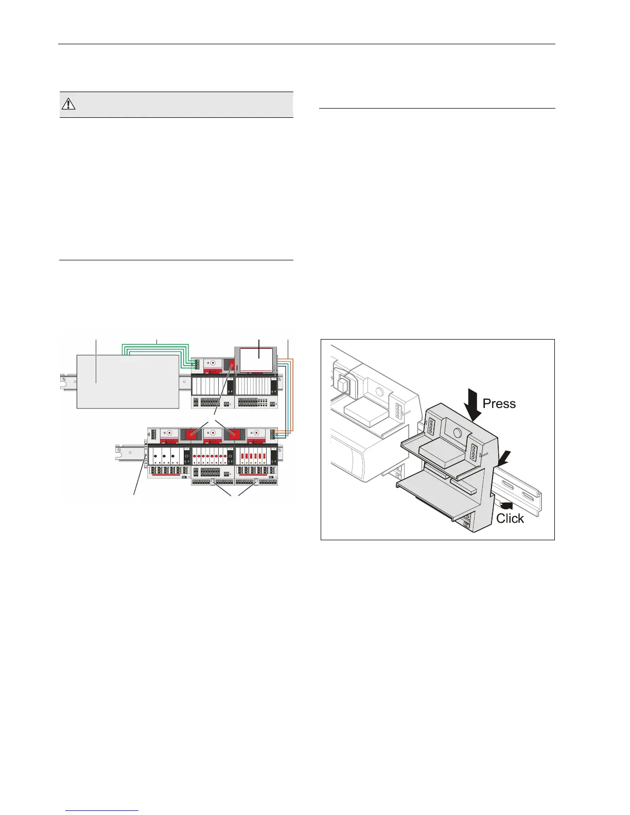
Fig. 6. CentraLine I/O Modules on DIN rails
Legend
1 Controller (e.g., LION, EAGLE, EAGLEHAWK, etc.)
2 Cable (power, L
ONWORKS / Panel Bus) connection from
controller to CentraLine I/O Modules
3 Swivel label holder
4 Cable connection between CentraLine I/O Modules on
separate DIN rails
5 Bridge connectors between CentraLine I/O Modules on
same DIN rail
6 Stopper (from 3
rd
-party supplier)
7 Auxiliary terminal packages
Mounting/Dismounting Modules / Sockets
Mounting Sockets
NOTE: When using both Panel Bus and LONWORKS Bus
I/O modules in a CentraLine controller system,
group both Panel Bus I/O modules and
L
ONWORKS Bus I/O modules, e.g., on different
rails.
NOTE: The mixed Panel Bus I/O modules are mounted
on the DIN rail in the same way as a terminal
socket.
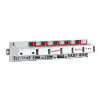
► Angle the terminal socket at the upper edge of the DIN
rail until it snaps in.
► Swing the terminal socket down and apply gentle force
until it snaps into position with an audible "click".
► Position controller module and terminal sockets flush with
one another along the rail.
► If desired, mount stoppers at the ends of the rail to
prevent sliding.
Fig. 7. Mounting terminal sockets
NOTE: Take care to not bend the Omega clamp, which
serves to establish the electrical contact with the
DIN rail and which located on the back of the
terminal socket.
Connecting Sockets
Controller, terminal sockets, and mixed I/O modules (exc.
CLIOP831A) on the same DIN rail can be connected
mechanically and electrically with bridge connectors.
Controller and terminal sockets on different DIN rails must
be connected using cables.