CENTRALINE I/O MODULES – INSTALLATION & COMMISSIONING INSTRUCTIONS
EN1Z-0973GE51 R0119 4
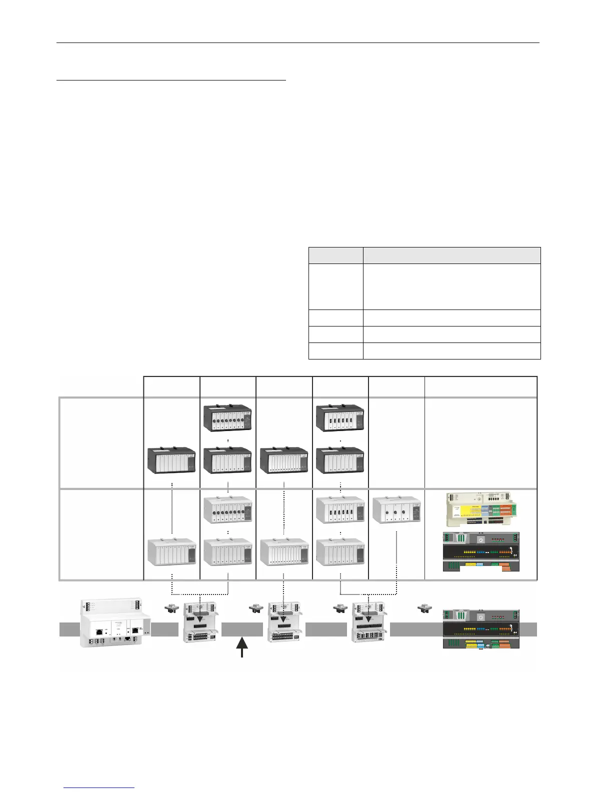
CentraLine I/O Modules and Sockets
Pluggable Panel Bus and LonWorks I/O Modules
There are two variants of pluggable I/O modules (consisting
of a terminal socket and a removable electronic module):
Panel Bus I/O modules with communication via Panel
Bus (light gray housings)
L
ONWORKS Bus I/O modules (dark gray housings) with
communication via L
ONWORKS (FTT10-A, link power
compatible) for easy integration and use with 3
rd
-party
controllers.
The firmware of pluggable I/O modules is automatically
updated by the controller, and the controller automatically
configures them as needed by the application.
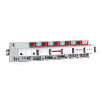
Mixed Panel Bus I/O Modules
Besides the pluggable I/O modules, there are also mixed
Panel Bus I/O modules. Specifically: the CLIOP830A and
CLIOP831A are mixed Panel Bus I/O modules featuring an
integrated terminal socket and a variety of inputs and
outputs.
The CLIOP830A has a light-gray housing.
The CLIOP831A has a black housing.
Their firmware is automatically updated and configured by
the controller, and the controller automatically configures the
mixed Panel Bus I/O modules as needed by the application.
Terminal Sockets
Pluggable I/O modules are mounted on the appropriate
terminal sockets (see Table 4). Pluggable Panel Bus I/O
modules and pluggable L
ONWORKS Bus I/O modules use the
same terminal sockets. The terminal sockets are available
with push-in terminals (XS821-22, XS823, and XS824-25) or
with screw-type terminals (XSU821-22, XSU823, and
XSU824-25). The mixed Panel Bus I/O modules (i.e. the
CLIOP830A with push-in terminals, and the CLIOP831A
with screw-type terminals) feature an integrated terminal
socket.
Color Coding
To distinguish modules and components, the following color
coding is used:
Table 2. Color coding of CentraLine I/O Modules
Color Part
Red
All user-accessible adjustable mechanical
parts (i.e., bridge connectors and locking
mechanism) and operating controls (manual
overrides, etc.)
Light-gray Panel Bus I/O modules (exc. CLIOP831A)
Black CLIOP831A mixed Panel Bus I/O module
Dark-gray LONWORKS Bus I/O modules
CLLIONLC01
MIXED I/Os
(with integrated electronic module)
pluggable
ANALOG OUTPUT
pluggable
ANALOG INPUT
pluggable
BINARY INPUT
pluggable
FLOATING
OUTPUT
pluggable
RELAY OUTPUT
XS821-22
XSU821-22
S823
SU823
S824-25
SU824-25
LonWorks or Panel Bus
CLIOP821A
CLIOL821A
CLIOP822A
CLIOPR822A
CLIOL822A
CLIOLR822A
CLIOP823A
CLIOL823A
CLIOP824A
CLIOPR824A
CLIOL824A
CLIOLR824A
CLIOPR825A
PANEL
BUS MODULES
LonWorks
BUS MODULES
123456789101112
B1 B2 B3 B4 B5 B6
B12
12
6
B11
11
5
B10
10
4
B9
9
3
B8
8
2
B7
7
1
DI
Binary Inputs
G1 G2
41 42
GND
Analog Out puts
AI2 AI3 AI4
14 15 16
AI1
17 18 19 20
13
Analog I nputs
AO5
AO1
AO6
AO2
AO7
AO3
AO8
AO4
21
25 26 27 28
22 23 24
DO
24V Relays
NO1NO2NO3NO4NO5NO6
CO1CO2CO3CO4CO5CO6
35
29 30 31 32 33 34
36 37 38 39 40
123456
Install. Instr.
MU1B-0473GE51
!
AI5 AI6 AI7 AI8
Honeywell
1234
5
6789101112
B1 B2 B3 B4 B5 B6
B12
12
6
B11
11
5
B10
10
4
B9
9
3
B8
8
2
B7
7
1
DI
Binary Inputs
G1 G2
41 42
GND
Analog Out puts
AI2 AI3 AI4
14 15 16
AI1
17 18 19 20
13
Analog I nputs
AO5
AO1
AO6
AO2
AO7
AO3
AO8
AO4
21
25 26 27 28
22 23 24
DO
24V Relays
NO1NO2NO3NO4NO5NO6
CO1CO2CO3CO4CO5CO6
35
29 30 31 32 33 34
36 37 38 39 40
1234
5
6
Install. Instr.
MU1B-0473GE51
!
AI5 AI6 AI7 AI8
Honeywell
CLIOP830A
CLIOP831A
CLIOP830A
CLIOP831A
Fig. 3. Overview of CentraLine I/O modules and terminal sockets