CENTRALINE I/O MODULES – INSTALLATION & COMMISSIONING INSTRUCTIONS
EN1Z-0973GE51 R0119
20
Addressing Panel Bus I/O Modules
During engineering, each Panel Bus I/O module (LION) /
each Panel Bus I/O module of a given type (EAGLE,
EAGLEHAWK) per RS485 interface is assigned its own
unique address. For the sake of clarity for maintenance
personnel, it is recommended that you address the Panel
Bus I/O modules in ascending order 0 through F.
Table 23. HEX switch settings and addresses
Hex switch 0 1 2 3 4 5 6 7
Address 01 02 03 04 05 06 07 08
Hex switch 8 9 A B C D E F
Address 09 10 11 12 13 14 15 16
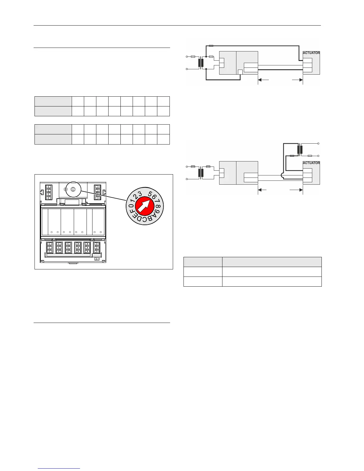
► Use the rotary HEX switch to set the address to the one
already defined using the engineering tool.
LOCK
4
4
Fig. 25. HEX switch location
NOTE: If the HEX switch is changed, the Panel Bus I/O
module will revert to its default configuration.
NOTE: In the case of L
ONWORKS Bus I/O modules, the
HEX switch is without function.
Connecting Field Devices
Connecting Field Devices with Power Supply
Depending on the distance from the controller, field devices
can be supplied by the controller or need a separate trans-
former, see Table 20 on page 10.
For fusing see section "Fusing Specifications" on page 9.
Example 1: Power Supply via Controller or Same
Transformer
24 V actuator connected to an analog output module
Less than 100 m away from the controller
Y (0...10 Vdc)
24 V0
230 V~
24 V~
max. 100 m
CONTROLLER
822A
1
2
9
1...8
GND
Y
24V
~
11...18
F1
F2
Fig. 26. Power supply of field devices via I/O module
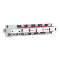
Example 2: Power Supply via Separate
Transformer
24 V actuator connected to an analog output module
100 … 400 m away from the controller
Y (0...10 Vdc)
24 V0
24 V0
230 V~
230 V~
24 V~
24 V~
max. 400 m
822A
1
2 1...8
GND
Y
24V
~
11...18
F1
F2
CONTROLLER
Fig. 27. Power supply of field devices via a separate
transformer
Cabling Field Devices
Cable Routing
Route low-voltage signal and output cables separately from
mains cables.
Table 24. Min. distances to power mains cables
Cable Min. distance
Shielded 10 mm (0.4 in.)
Unshielded 100 mm (4 in.)
All low-voltage signal and output cables should be regarded
as communication circuits in accordance with VDE 0100
and VDE 0800 (or NEC or other equivalent).
Cable Shielding
If the general guidelines for cable routing are observed, it
is not necessary to shield field device signal and power
supply cables.
If, for whatever reason, the routing guidelines cannot be
observed, the field device signal and power supply
cables must be shielded.
– Shielding of cables leading to field devices must be
grounded only at the cabinet end.
– The shield must not be terminated at the controller.