CENTRALINE I/O MODULES – INSTALLATION & COMMISSIONING INSTRUCTIONS
19 EN1Z-0973GE51 R0119
Com a
Com b
24V~
24~0
Com a71
75
72
76
73 77
74
78
Com b
24V~
24~0
Com a
71
75
72
76
73 77
74 78
Com b
24V~
24~0
Com a71
75
72
76
73 77
74
78
Com b
24V~
24~0
Com a
71
75
72
76
73 77
74 78
Com b
24V~
24~0
Com a71
75
72
76
73 77
74
78
Com b
24V~
24~0
Com a
71
75
72
76
73 77
74 78
Com b
24V~
24~0
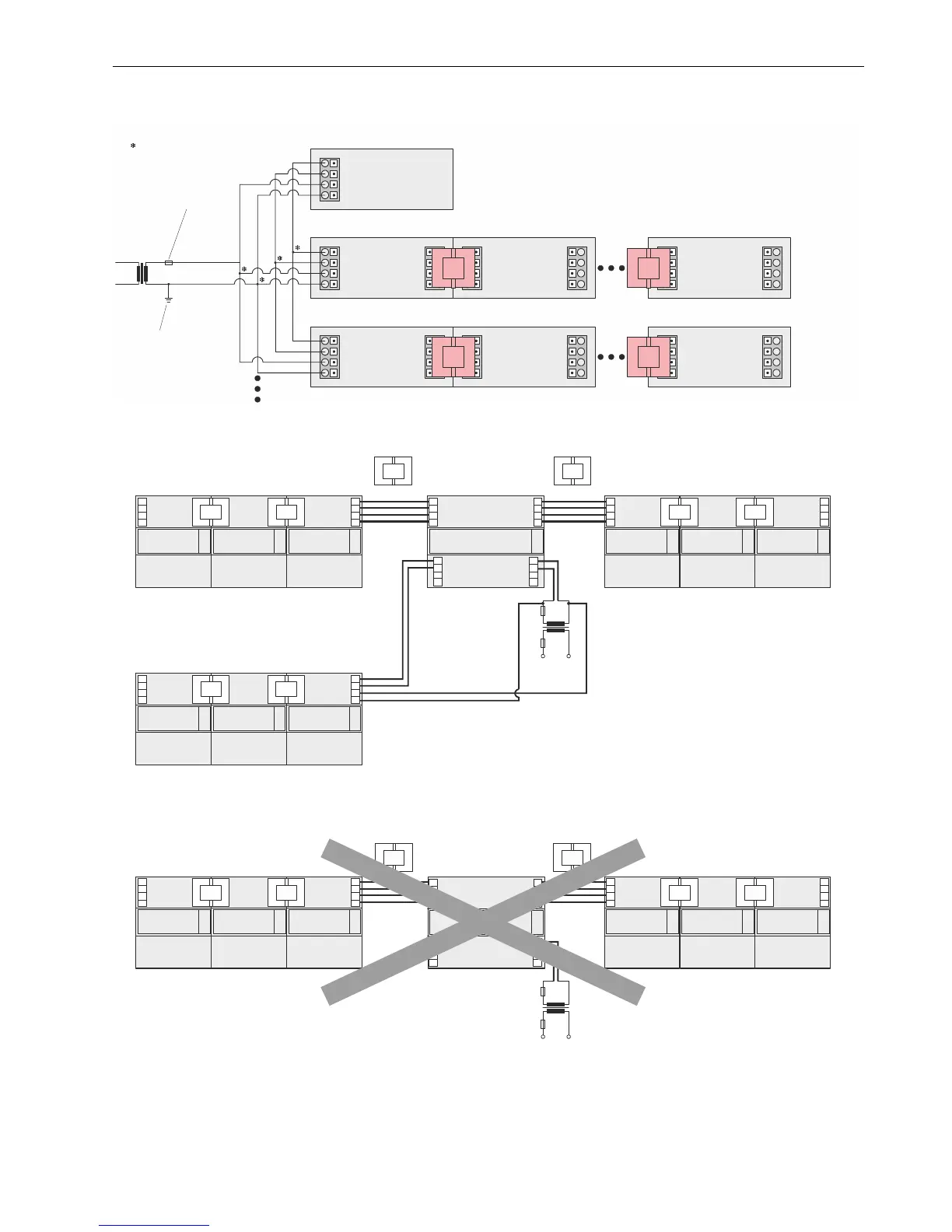
CONTROLLER WITHOUT
BRIDGE CONNECTOR
CentraLine I/O Module CentraLine I/O Module CentraLine I/O Module
MAX. 10
MODULES
PER ROW
MAX. 10
MODULES
PER ROW
CentraLine I/O Module CentraLine I/O Module CentraLine I/O Module
SECONDARY FUSE
RECOMMENDED
NOISE-FREE
EARTH GROUND
(1 PER SYSTEM, ONLY)
TWIN FERRULES
MAY BE USED FOR
THESE CONNECTIONS
Fig. 22 Wiring controllers not supporting bridge connectors (for fusing, see section "Fusing Specifications" on page 9)
73
71
72
74
77
75
76
78
73
71
72
13
11
14
12
3
1
4
2
74
77
75
76
78
73
71
72
74
77
75
76
78
73
71
72
74
77
75
76
78
XF...
CONTROLLER
Panel Bus I/O modules Panel Bus I/O modules
LonWorks Bus I/O modules
73
71
72
74
77
75
76
78
73
71
72
74
77
75
76
78
73
71
72
74
77
75
76
78
73
71
72
74
77
75
76
78
73
71
72
74
77
75
76
78
73
71
72
74
77
75
76
78
Fig. 23. Mixed bus system – correct wiring
73
71
72
74
77
75
76
78
73
71
72
13
11
14
12
3
1
4
2
74
77
75
76
78
73
71
72
74
77
75
76
78
73
71
72
74
77
75
76
78
Panel Bus I/O modules LonWorks Bus modules
73
71
72
74
77
75
76
78
73
71
72
74
77
75
76
78
73
71
72
74
77
75
76
78
CONTROLLER
Fig. 24. Mixed bus system – incorrect wiring