CENTRALINE I/O MODULES – INSTALLATION & COMMISSIONING INSTRUCTIONS
EN1Z-0973GE51 R0119
18
PANEL
I/O
PANEL
I/O
PANEL
I/O
75
75
71
76
7672
77
7773
78
78
74
MAX. 40 m
24 V0
CPU
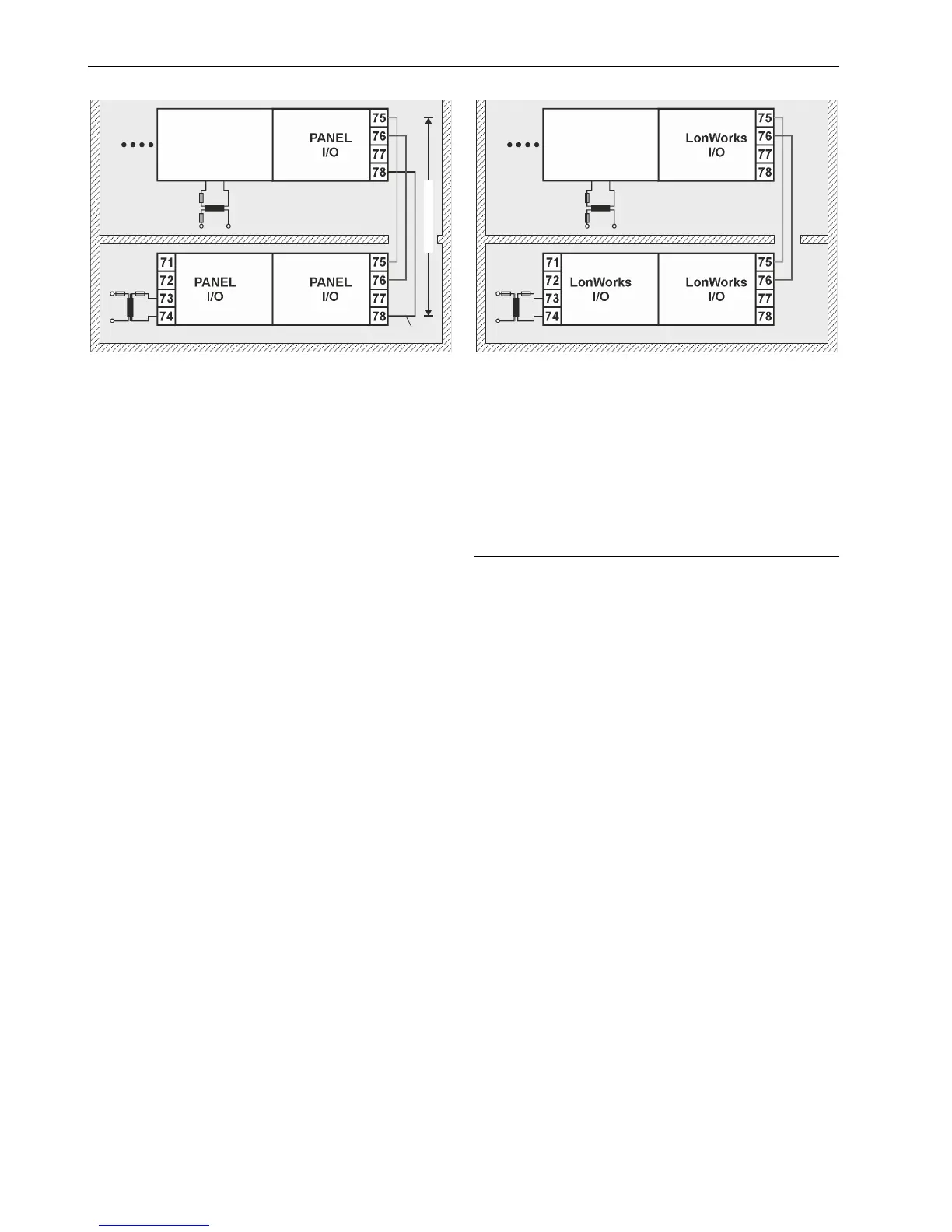
Fig. 20. Wiring the Panel Bus I/O modules in separate
rooms
Max. Cable Length
The max. cable length for connecting room 1 and room 2 is:
40 m (any type of cabling and topology, incl. star and loop
topology, possible; no additional end termination
permitted);
1200 m (mandatory twisted-pair or telephone cable and
daisy chain topology; controller must be positioned at one
end of the Panel Bus, and an end termination of 120 Ω
positioned at the other end).
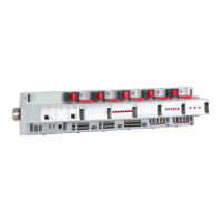
LonWorks Bus I/O Modules in Separate Rooms
In this scenario, only communication lines must be connected
between the rooms.
► Connect the last module of room 1 to the first module of
room 2:
– via communication terminals 71, 72 or 75, 76
LonWorks
I/O
LonWorks
I/O
LonWorks
I/O
75
75
71
76
7672
77
7773
78
78
74
CPU
Fig. 21. Wiring the L
ONWORKS Bus I/O modules in
separate rooms
Max. Cable Length
For max. cable lengths and cable specifications of the
communication lines, see Table 18 and
Table 19 on page 10.
Connecting Panel Bus and LONWORKS Bus
Mixed Controller Systems
Connecting I/O Modules with Each Other
For connecting the I/O modules with each other, proceed as
described for single bus controller systems on page 17.
Connecting I/O Modules to the Controller
Panel Bus I/O Modules
► Connect communication terminals 71/72 or 75/76 of Panel
Bus I/O modules to the communication terminals of the
given controller using either
– Bridge connectors (for flush mounting on a single DIN
rail) or
– Cables (for separate mounting, e.g., on multiple rails,
separate cabinets, etc.).
LONWORKS Bus I/O Modules
► Connect communication terminals 71/72 or 75/76 of
L
ONWORKS Bus I/O modules to the LONWORKS terminals of
the given controller using cables and terminate properly
(see also section "L
ONWORKS Bus Termination Modules"
on pg. 9).