CENTRALINE I/O MODULES – INSTALLATION & COMMISSIONING INSTRUCTIONS
5 EN1Z-0973GE51 R0119
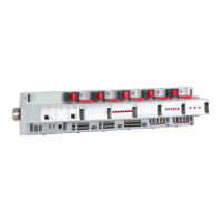
CentraLine I/O Module Overview
Table 3. Overview of CentraLine I/O modules
Panel Bus
module
LONWORKS
Bus module
Description Inputs Outputs Manual controls LEDs
1)
CLIOP821A CLIOL821A Analog input module 8 – – –
CLIOP822A CLIOL822A Analog output module – 8 – 8 status LEDs
CLIOPR822A CLIOLR822A Analog output module – 8 8 Manual overrides 8 status LEDs
CLIOP823A CLIOL823A Binary input module 12 – – 12 status LEDs
CLIOP824A CLIOL824A Relay output module – 6
2)
– 6 status LEDs
CLIOPR824A CLIOLR824A Relay output module – 6
2)
6 Manual overrides 6 status LEDs
CLIOPR825A – Floating output module – 3 3 Manual overrides 3 pairs of status LEDs
CLIOP830A -- Mixed I/O module 20 14 -- 18 status LEDs
CLIOP831A -- Mixed I/O module 20 14 -- 18 status LEDs
1)
In addition to the power LED and service LED
2)
Changeover outputs
Corresponding Terminal Sockets
Table 4. Pluggable I/O modules and corresponding terminal sockets
I/O module CLIOP/CLIOL… Socket Scope of delivery
…821A
XS821-22 with push-in terminals
XSU821-22 with screw-type terminals
1 terminal socket,
1 bridge connector
1 swivel label holder
…822A
…823A
XS823 with push-in terminals
XSU823 with screw-type terminals
1 terminal socket,
1 bridge connector
1 swivel label holder
…824A
XS824-25 with push-in terminals
XSU824-25 with screw-type terminals
1 terminal socket,
1 bridge connector
1 swivel label holder
1 cross connector
…825A
Manual Overrides as per EN ISO 16484-2:2004
The manual override switches and potentiometers of the output modules (…R822A, …R824A, and CLIOPR825A) support direct
operation as per EN ISO 16484-2:2004, section 5.4.3 "Local Priority Override/Indicating Units."
Specifically, the positions of the manual override switches and potentiometers directly control the outputs – independently of the
connected controller or HMI. When a manual override switch or potentiometer is not in its default position ("auto"), the cor-
responding output LED will blink continuously, and the output module will send a feedback signal with the status "manual
override" and the given override position to the connected controller (which will then also store this information in its alarm
memory).
NOTE: When updating the firmware of output modules, their outputs are turned OFF – regardless of the position of their
manual override switches and/or potentiometers.
NOTE: In the following, e.g., …822A is used to summarize all analog output modules (Panel Bus/L
ONWORKS Bus,
with/without manual overrides).