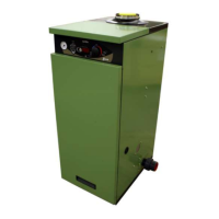
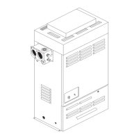
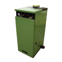
Condensing Pool Heater Genie S
Space required for installation and
servicing:
Left, right and above 300mm
Front 800mm
Suggested procedure:
Site to suit the pool, terminal, plume and condensate
drain limitations. The Terminal position should follow
BS 5440 and be at least 600mm away from any
opening or obstacle.
1. For an indoor installation only : Mark & Drill
Flue hole. (See Fig. 3.1 and 3.2 for dimensions)
2. Fix the Heater to the fl oor using the holes pro-
vided in the front channel.
3. The Heater is provided with an Electrical Plug and
lead. This can be connected to a suitable supply
as detailed on Page 5. If it is required to sepa-
rately time the operating of the Heater this can be
achieved as follows:
Remove Front Top Panel after releasing the
retaining M5 screw under the lip.
Remove the Electrical Cover to access the
Mains connector.
Pull out the Mains connector and replace
the Mains lead and link wire with a
Permanent and Switched live supply.
See Fig 11.0
4. Pipe to the 22mm gas connection. A gas isolating
valve is provided on the Heater Gas Valve.
5. Plumb to the Pool Pump and Filter.
6. Fill Primary system with water using the supplied
hose connector. The Heater is supplied with one
litre of Sentinel X500 Inhibitor/ Anti-Freeze in the
pipework.
7. IMPORTANT. Remove the air from the primary
through the Air Vent on the right-hand Side Panel
and the Vent on the top of the Primary Heat Ex-
changer. (See Fig 8.0) by operating the internal
pump in short one second bursts, venting, then
pumping, until it has all been removed. There is
a special button (See Fig. 8.1) for operating the
pump on its own, under the chassis on the pres-
sure gauge side. To operate the Mains must be
connected and on.
8. Test for leaks.
9. Replace the Electrical Cover and Panels.
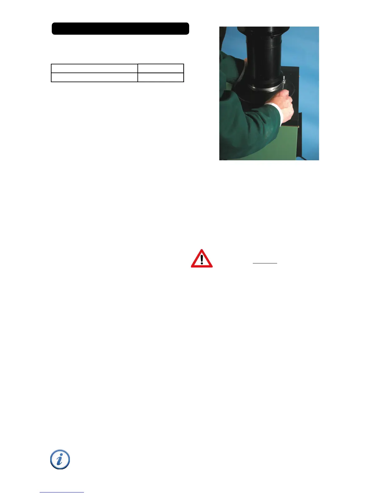
Assembly of the Outdoor Terminal
A specifi c Outdoor Top Terminal must be used for an
outdoor installation. There must be at least 600mm
clearance around the terminal and complete clear-
ance above. The Outdoor Top Terminal is a push fi t
into the Flue Adapter and locked in position with a
clamping ring. (See Fig. 3.0 & 3.3)
If lubrication is required only Centra Cerin or
silicone grease should be used.
7
All Other Flue Systems
The maximum Flue Equivalent Length (FEL) permit-
ted is 20 metres, horizontal or vertical. The compo-
nent parts have the following FELs:
1 metre of concentric fl ue 1.0
2 metres of concentric fl ue 2.0
A 45 degree concentric bend 1.1
A 90 degree concentric bend 1.5
A concentric Roof Terminal 3.3
A concentric Wall Terminal 3.9
Sum of the Flue Equivalent Lengths used in
the design this must not exceed 20 metres.
All items assemble by a push fi t/clamp system. If it is
required to lubricate the seals only Centra Cerin sup-
plied by the manufacturer or Silicone Grease should
be used. The pipes should be assembled so the
socket end is always furthest from the Heater. Flues
should be supported by brackets every metre of run.
Horizontal fl ues should incline back to the Heater by
3 degrees (5mm in 100mm)
Wall Terminal
The Horizontal Wall Terminal is supplied with two
rubber wall plates, one for inside and one for the
outside. The core drill diameter required is 175mm
and should incline upwards to the outside.
Because of the incline the height of the centre of the
fl ue hole on the wall is determined by the distance of
the heater from it. Calculate as follows:
1. Ensure service clearance is available.
2. Fit the 90 degree elbow to the heater and
measure from its outlet face to the wall.
3. Add 5 mm for every 100 mm distance.
Example: Distance measured = 480 mm
(5 x 480) / 100 = 25 mm
Flue centre 1065 + 25 = 1090mm
If it is required to reduce the length of the Terminal
the minimum overall length is 300mm. The Flue duct
should be cut 10mm longer than the Air duct.
Fig. 3.0
INSTALLATION OF HEATER