Condensing Pool Heater Genie S
14
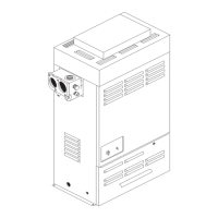
Condensate Connection
The direction of the plastic condensate drain pipe
connection can be altered from the factory position
on the left, to the right.
• Remove the blanking plate from the right hand
side (See Fig. 3.1).
• Loosen the two screws holding the Trap
bracket and swivel the trap through 90 degrees.
• Secure the bracket and fi t the supplied 40 mm
pipe.
• Example installations are shown in Fig 7.0.
• Fit blanking plate to the left hand side (See Fig
7.1).
Where possible an internal termination of the con-
densate discharge pipework should be used. If this
is not possible external pipes should be kept as
short as possible and insulated.
Where fi tted in pipework that includes another trap
or a pump, for example the fi lter backwash pipework
to drain, an Air Break should be fi tted between the
Heater and that pipework. Avoid connecting to a
kitchen sink trap as the solids and fats in the drain
will cause a blockage.
It is permissible to connect to an external gully or
rain water hopper provided they connect to a com-
bined system.
The condensate should not be run into a ‘grey water’
recycle system.
If the condensate pipe is connected to a stack it
should join not less than 450 mm above the foot of
the stack. In addition it should be positioned so there
no chance of cross-fl ow to another connection.
Installation pipework must be in 40 mm Hunter plas-
tic pipe to a suitable drain location with a gradient
of 2.5° (45mm/ metre run) minimum. If connected to
another drainage trap, an air break is required be-
tween the Heater drain and that trap. (See Fig.7.0 &
7.1). External runs, should, if possible, be insulated
to help prevent the condense liquid freezing.
Check during commissioning that there is a leak free
working connection from the Heater to the drain.
The simplest way to do this is to carefully pour some
water into the boiler fl ue and check it emerges at the
drain. This will also fi ll the trap ready for operation.
Electrical Connections
WARNING: The appliance
MUST be earthed.
All wiring for the Heater and system controls MUST
conform to I.E.T. Wiring Regulations, and work
should be tested using a suitable meter, for Earth
Continuity, Polarity, Short Circuit and Resistance to
Earth.
The Heater supply must be through a common iso-
lator, a double pole 5A fused isolating switch with a
contact separation of 3mm minimum on both poles.
The cable used should be no less than 0.75mm
2
to
BS.6500 PVC, 3 core, and fi xed ensuring the earth
connection is longer than the Live and Neutral.
Access to the Heater connections is made by the
removal of the Front Top Panel and the Electrical
Chassis cover, two screws.
The simplest and most fl exible control scheme is to
use a Certikin CCP01 Control Unit. This provides an
electrical safety trip and timer with outputs for the
Heater, lights and an auxilary voltage free output. It
is pre-wired and tested and provided in a standard
IP55 plastic control box.
The Heater’s internal wiring is shown in Fig.11.0.
Connections are as follows :-
4 Way Terminal Supply Connection
Earth
N Mains Neutral
SL Switched Live
L Permanent Live
A factory installed link has been fi tted between SL
and L which should be removed if the Heater is to
have its own switched supply.
For systems using an external programmer, the
electrical wiring should follow the relevant control
manufacturer’s recommendations, with the switched
live from the controls returning to SL in the 4 way
push-fi t connector.
It is possible to connect several Heaters together
using the Multiple Heater Kit. Details for the parts
and installation of this kit are given on Page 18.