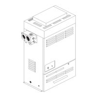
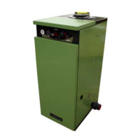
Condensing Pool Heater Genie S
• Heat Exchanger Combustion Temperature
Sensor
• Flue Thermostat
• Ignition Control
• Gas Valve
• Fan
• Pump
• Expansion Vessel
• Heat Exchanger
• Secondary Heat Exchanger.
On the Electrical Chassis
To access these items fi rst remove the Front Top
Panel and then the Chassis Cover.
Fuse (See Fig. 13.0)
There is one in line 3A fuse on the 24V supply
between the Transformer and the Pool Thermostat.
The Fuse Holder bayonets apart to allow its replace-
ment.
Transformer (See Fig. 13.0)
The Transformer includes its own, internal thermal
fuse on the primary. If this has gone open circuit the
cause should be established before replacing the
Transformer.
• Disconnect from the terminal strip and fuse
holder.
• Undo the two screws holding it to the chassis
and replace.
Pool Thermostat (See Fig. 13.0)
• Pull off the pool thermostat Knob.
• Release rear retainer by undoing the wing nut.
• Pull off all the PCB connectors.
• Slide out the thermostat.
• Replacement is the reverse.
Condensate Pressure Switch
(See Fig. 13.0)
• Undo the single fi xing screw.
• Pull off the two electrical connectors and transfer
to the new switch. They connect to the ‘C’ and
‘NC’ connections.
• Replacement is the reverse
Relay
(See Fig. 13.0)
• Pull off the three electrical connectors and trans-
fer to the new relay.
• Undo the two fi xing nuts and secure new relay in
position.
Heater Components
The remainder of the parts can be accessed
through the front.
28
Heat Exchanger Flow Sensor
This is located on the front connection to the heat exchang-
er. (See Fig.14.4)
• Un-clip the sensor from the connection.
• Transfer the push on electrical connectors to the
replacement and clip back on.
Heat Exchanger Pool Sensor
This is located in a pocket in the ‘From Pool’ side of the
Secondary Heat Exchanger. (See Fig.14.6)
• Pull out the retaining slipper, and pull out sensor.
• Disconnect from the six way terminal strip on the
electrical chassis.
• Replacement is the reverse.
Water Pressure Switch
This is located on the Inlet connection to the secondary
heat exchanger and its removal will require the draining or
isolation of the pool water in the heater. (See Fig.14.6)
• Pull off the electrical connectors
• Unscrew from the secondary heat exchanger.
• Replacement is the reverse.
• If the water pressure switch needs adjustment See
Page 12 for details.
Control Thermostat
This is located on the outlet connection of the heat ex-
changer. (See Fig.14.4)
• Un-clip the sensor from the connection.
• Transfer the push on electrical connectors to the
replacement and clip back on.
Heat Exchanger Combustion
Temperature Sensor
This is located on the top of the heat exchanger, on the
right hand side. (See Fig.14.1)
• Release the electrical connector by pressing the
latch and pulling up.
• Twist the Sensor a quarter turn clockwise and
withdraw.
• Replacement is the reverse.
Ensure the O ring seal is fi tted correctly to the
replacement before fi tting
Flue Thermostat (manual reset)
This is located on the Flue Adapter. (See Fig.14.1).
• Pull off the electrical connectors.
• Slide out from under the clip.
• Replacement is the reverse.
Ignition Control (See Fig.14.3)
• Undo the single screw holding the ignition control.
• Release the two electrical connectors by pressing
the latch and pulling apart.
• Pull the ignition control away from the gas valve.
• Replacement is the reverse.
Gas Valve (See Fig.14.3)
• Remove the ignition control, see above.
• Release the gas cock by undoing the four shoul-
der bolts holding it to the Gas Valve.