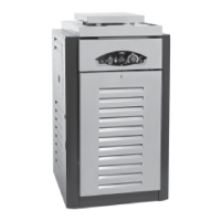
Condensing Pool Heater Genie S
29
• Remove the Off set tube from the Gas Valve and
unscrew the Off set Connector and transfer to the
new Gas Valve.
• Release the Gas Valve from the Venturi by undoing
three screws. (See Fig.14.3)
IMPORTANT: Ensure the rubber seal
(and orifi ce if propane) is transferred
from the old Valve and placed between
the Venturi and Gas Valve before
assembly.
• Replacement is the reverse.
• Fire up the Heater and check for gas leaks.
• After fi ve minutes check the rate and combustion
is correct to the Data table. (inside cover). Adjust
using the throttle on the Gas Valve, (See Fig.14.3).
Fan (See Fig.14.2)
• Remove the two electrical connectors on the Fan.
• Remove the two screws holding the Venturi to the
Fan.
• Undo the four nuts holding the Fan to the Heat
Exchanger and withdraw. (See Fig.14.2)
• Transfer the Venturi gasket to the new fan.
• Replacement is the reverse.
Venturi (See Fig.14.2)
• Remove the Ignition Control and Gas Valve, see
above.
• Pull off the Air Tube (See Fig.14.3)
• Undo the two screws holding the Venturi to the
Fan and remove.
• Ensure the gasket is transferred to the new venturi or
positioned on the Fan before positioning the replace-
ment.
• Replacement is the reverse.
• Fire up the Heater and check for gas leaks.
• After fi ve minutes check the rate and combustion is
correct. (see inside cover). Adjust using the throttle
on the Gas Valve if required. (See Fig.14.3).
Pump (See Fig.14.0)
• Drain the primary waterside of the Heater.
• Disconnect the Pump mains lead from the six way
connector in the Electrical Chassis.
• Undo the two water connections of the pump and
remove.
• Transfer the mains lead to the new Pump.
• Replacement is the reverse.
IMPORTANT : It is essential that all the
air is removed from the heat exchanger
before the heater is fi red. Operating the
heater which contains air inside may
damage the heat exchanger and
invalidate the warranty.
Expansion Vessel (See Fig.14.0)
• Remove the single screw holding the retaining strap.
• Release the fl exible hose connection to the Vessel
and remove it.
• Replacement is the reverse.
Heat Exchanger (See Fig.14.0)
• Remove the Expansion Vessel
• Remove the spacer below the Secondary Heat
Exchanger by removing the two screws and pull-
ing forward.
• Release both the Heat Exchanger Demountable
connections. (See Fig.14.5)
• Undo the screws holding the panels around the
Demountable connections. (See Fig.14.5)
• Lower the pipework away from the Heat Ex-
changer.
• Remove the Front Top Panel and disconnect the
Flue Thermostat connections.
• Pull the Air Duct and Flue up and away from the
Heater Flue Adapter.
• Disconnect the Heat Exchanger Combustion
Sensor by pressing the latch and pulling off .
• Remove the four screws holding the Rear Top
Panel.
• Lift the Rear Top Panel with the Flue Adapter
clear of the Heat Exchanger.
• Remove the Fan, Gas Valve and Ignition Control-
ler.
• The Heat Exchanger is now only retained by the
two side brackets and releasing the four front
screws will enable it to be pulled forward. Before
releasing ensure there is support available.
• Replacement is the reverse.
IMPORTANT : In order to maintain
suffi cient frost protection levels it is
recommended that after a drain down
the heater is re-fi lled with a suitable
anti-freeze. The manufacturer
recommends Sentinal X500.
Secondary Heat Exchanger (See Fig.14.0)
• Drain the pool side suffi ciently so that the
Heaters Pool Connections can be released.
• Remove the Case retaining Plates around the
Heater’s Pool Connections.
• Drain the primary system with the drain cock
provided. Ensure an air vent is open to fully re-
lease the water.
• Remove the Pool Sensor from the Secondary
Heat Exchanger.
• Remove the Expansion Vessel.
• Remove the two fi xing screws holding the Spacer
below the Secondary.
• Pull out forwards the Spacer and remove.
• Undo the primary Compression connections on
the Secondary Heat Exchanger and allow it to
drop off its connections and remove.
• Remove the four screws fi xing the Secondary
Heat Exchanger to its mounting plate.
• Replacement is the reverse.