Condensing Pool Heater Genie S
Winterisation
Turn off the Mains electricity and Gas Supply.
As supplied the Heater includes one litre of Sentinel
X500 Inhibitor/Anti-freeze, this is suffi cient to protect
the Heater down to -10°C. It is recommended that
this is maintained and so should be replenished if
there is a loss of primary water. See Fig 14.0
Draining the Heater can be achieved by fi tting the
drain assembly in place of the double check valve/
hose connector. The Condensate Syphon can be
drained by removal of its Drain Cap. See Fig 7.1
Electricity Supply
Wiring external to the appliance MUST be in accord-
ance with the current I.E.T. Wiring Regulations and
any Local Regulations that apply.
The Heater is supplied with a plug and lead for 230V
~ 50Hz. Single phase. Fuse rating is 5A.
The method of connection to the mains electricity
supply MUST facilitate complete electrical isola-
tion of the Heater, preferably by the use of a fused
double pole switch having a 3mm (1/8in.) contact
separation in both poles and servicing only the
Heater and its controls.
The point of connection to the mains should be
readily accessible and adjacent to the Heater.
Where a Heater is installed in a room
containing a pool or shower, the appliance,
any electrical switch or appliance control
utilising mains electricity should be so
situated that it cannot be touched.
6
Condensate Drain
See Fig. 7.0, and 7.1
A 75mm condensate trap is provided on the Heater
and is satisfactory when connected to Soakaways,
Gullies, Rainwater Pipework and Internal Drainage
systems. All pipework and fi ttings in the condensate
drainage system MUST be made of plastic, unless
they carry other liquid waste. No other materials
may be used. The pipework should be insulated if
run out of doors.
The drain outlet on the boiler is :
40 mm Hunter waste pipe.
Pool Pump & Pipe work
The Heater is an indirect design and uses two very
high performance heat exchangers. The pool water
passes through the Secondary, the water in the
Primary is completely separate. The Heaters con-
trols modulate the input when approaching the set
temperature for greater accuracy and economy. It
is recommended that pool pump overrun is used to
maximise the life of the Heater.
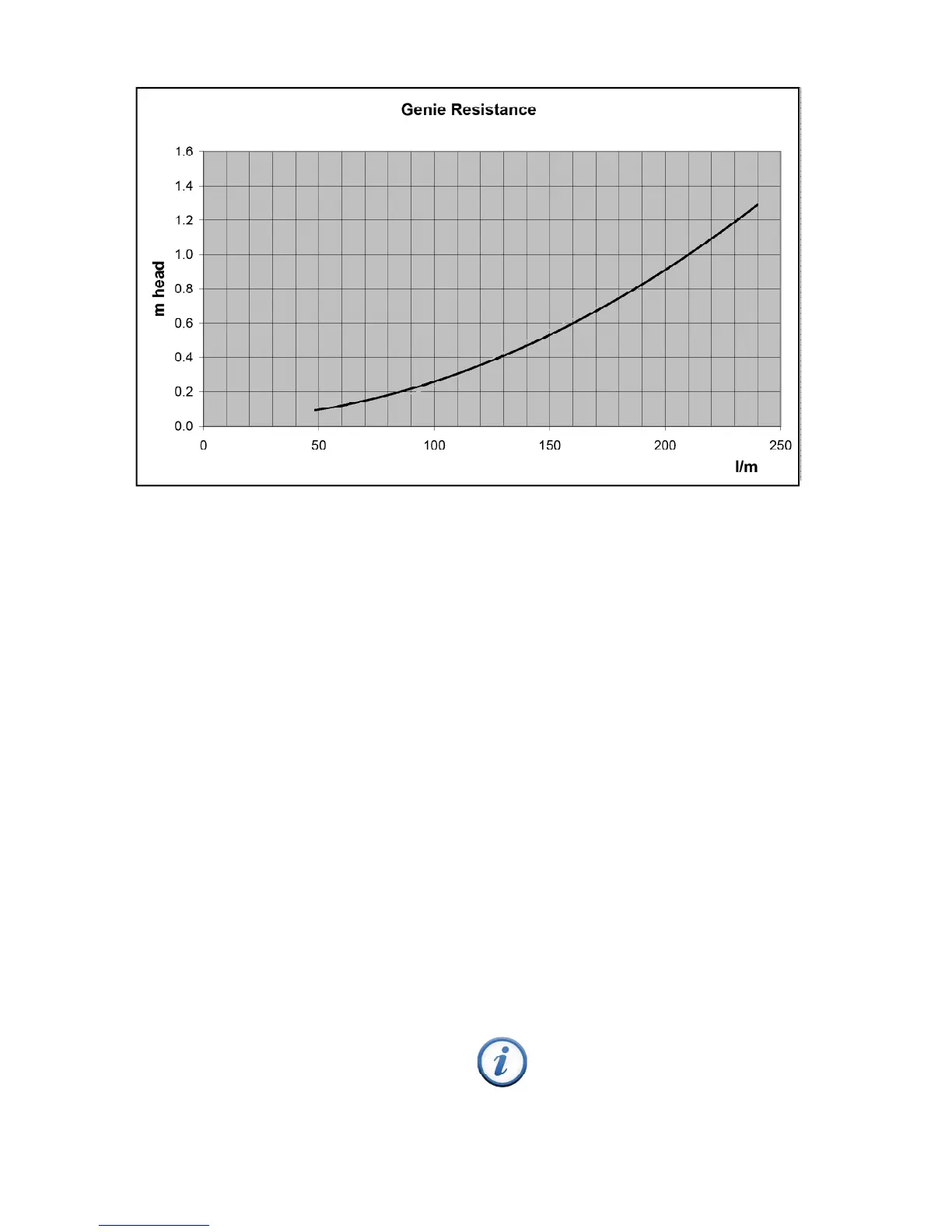
If a new pump is being fi tted consult the Pressure
Loss graph (Fig 2.0) to determine its size.
The Heater is provided with both 1½” and 50mm
plastic pool connections. As built the connections
are ‘From Pool’ on the left, ‘To Pool’ on the right,
however these can be easily reversed.
With the exception of automatic dosing equipment,
the Heater should be plumbed as the last piece of
equipment before the pool.
It is permissible to fi t an isolating valves on the pipe-
work on either side of the Heater. In these circum-
stances it is recommended to fi t a fl ow switch in the
Heaters Mains supply.
Fig. 2.0