Condensing Pool Heater Genie S
SERVICING
Routine Service
To ensure continued effi cient operation of the ap-
pliance it is recommended that it is checked and
serviced at regular intervals.
The frequency of servicing will depend upon the
particular installation and usage but in general every
2,000 hours of operation should be the maximum.
It is law that any service work should be carried out
by Registered personnel.
1. Clean burner and combustion chamber.
2. Check condition of ignition spark and sensing
probe.
3. Check boiler pipework joints for leaks.
4. Check the Air duct and Flue seals.
5. Check condensate syphon and pipework for leaks.
6. Check the Gas Rate.
7. Check the combustion CO and CO2.
8. Reset the Service Hours counter in the control.
Follow the procedures given in Changing Components
for parts removal in addition to the following notes.
In all cases, before work commences turn off the
Mains Electricity and Gas Supply.
Burner & Combustion Chamber
To view the burner and the inside of the Heat Ex-
changer it is suggested you remove the front of the
Heat Exchanger complete with the Fan and Gas
Valve:
• Remove Door and Front Top Panel
• Disconnect Gas cock fl ange form Valve.
• Unplug Fan electrical connectors.
• Remove Air tube from Flue Adapter.
• Undo cover over Ignition Control connections
and remove the two connectors.
• Pull off the Earth Lead connection on the Valve
and Heat Exchanger.
• Undo the four nuts holding the Heat Exchanger
front and withdraw.
• Assembly is the reverse.
• Reset the Service Hours Counter. (See Service
Mode, page 23)
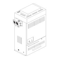
Spark & Sense Electrode
• Turn off the Heater.
• Pull off the HT Lead.
• Undo the two screws retaining the electrode
assembly and carefully withdraw. The spark gap
should be 3.0 mm ± 0.5. (See Fig 12.0)
• Assembly is the reverse, ensure the gasket
is correctly placed.
Pipework
IMPORTANT. The Heat Exchanger
connections are made using O rings and
should not be strained in any direction.
Any strain will result in damage to the heat
exchanger and will not be covered by the
warranty.
Condensate Syphon
The lower bowl of the Syphon can be unscrewed,
examined and cleaned.
Air Duct & Flue Seals
A visual inspection should establish there are no
leaks around any of the seals, including the fl exible
Air Duct to the Venturi.
Gas Rate & Combustion
See the Data table on Page 1 for the correct val-
ues.
A Combustion sample point is provided on the front
of the Flue Adapter. (See Fig.14.1)
Changing Components
There is only one fuse, the remainder
of the controls are not repairable and
if not operating must be replaced.
In all cases, before work commences turn off the
Mains Electricity and Gas Supply.
The following items can be replaced:
• Fuse, 24V supply.
• Transformer.
• Pool Thermostat.
• Condensate Pressure Switch.
• Relay.
• Pool Temperature Sensor.
• Heat Exchanger Flow Sensor.
• Water Pressure Switch.
• Control Thermostat.
• Overheat Thermostat.
27
Fig 12.0
 Loading...