Condensing Pool Heater Genie S
12
Terminal Guard
The fl ue products from this appliance are very
low temperature so a guard is only required if the
terminal is in a position where it may be damaged.
A suitable guard is available from:
TFC Ltd. 01732 351555, Model DK6
Roof Terminal
The Vertical Roof Terminal should be fi tted in a
minimum of 300mm clear unobstructed space. It is
not permitted to alter the construction of the Ter-
minal, above the roof line, however the concentric
section below the roof line can be altered to suit
the installation.
It is recommended that:
1. The Installation of the fl ues are completed
before their connection to the Heater. This will
ensure that any debris that gets into the fl ues
can be cleared.
2. That bends in vertical fl ues are 45 degrees.
3. Flues may be reduced in length by cutting. The
inner Flue pipe should be cut so it is 5 to 10mm
longer than the outer Air duct. It will ease as-
sembly if the cut edges are cleaned, chamfered
and greased before assembly.
Plumbing
The heater requires water fl ow and pressure to op-
erate properly. It must therefore be installed down-
stream of the fi lter and pump. A typical installation is
plumbed as follows:
1. The Pump outlet is plumbed to the inlet of the Filter.
2. The outlet side of the Filter is then plumbed to the
inlet of the Heater.
3. The outlet of the Heater is plumbed to the return
line to the pool or spa. The Pump, Filter and Heater
are plumbed in series.
If it is necessary to install a valve on the return to
the pool then it is recommended that a fl ow switch
is installed and interlocked with the Heater supply.
The Heater must be located so that any water leaks
will not damage the structure of adjacent area. The
heat shunt connections of the Heater, can be made
in standard plastic 1½” or 50mm pipe supplied de-
mountable.
Use the pressure loss chart on page 6 to specify a
suitable pump.
Connection to the Heater can be made from either
left to right, or right to left, it is supplied with the
‘From Pool’ connection on the left. To change, undo
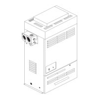
Fig. 5.0
the demount connection on the right, complete
with blanking plates, and swap with the connec-
tions on the left. Ensure that the Pool Sensor is
correctly positioned in its pocket after the change.
Flow Rate
The Heaters have a very low resistance to the
Pool Water fl ow and will tolerate a wide range of
fl ows.
The minimum recommended fl ow is:
80 litres/min
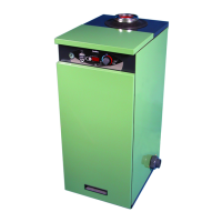
Pressure Switch
The Heater is protected by an adjustable wa-
ter pressure switch that has to close before the
Heater will operate.
It is very important to verify that it turns
off when the water fl ow is interrupted.
It has an adjustment range equivalent to ±1.5 me-
tres. The switch is factory set for most conditions
but can be altered if required:
1. With the pump on turn the knurled nut clock-
wise until a click is heard.
2. Turn the nut anti-clockwise a quarter of a turn.
3. Turn the pump on and off to check the switch
operates correctly.