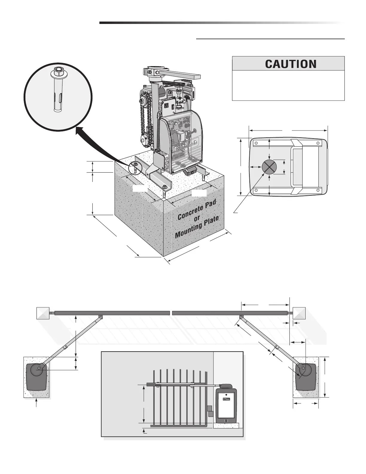
10
Below the Frost
Line Check all
Local Codes
Concrete Anchors
1/2" x 3-1/2"
6"
Above
Ground
28"
Post
Concrete Pad
Bracket Height
Concrete Pad Height
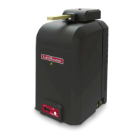
Long Arm
Using Standard Arm
Short Arm
Hinge Center
Drawing not to scale
24"
Sample of Standard Arm Attachment
(See next page for layout)
28"
46"
25"
35.5"
29.5"
24"
11"
10"
27.5"
Long Arm is
on Top of
Bracket!
Bottom of CSW
2"
Outside Property
Inside Property
14"
3-5/8"
5-1/4"
3-7/8"
5-1/4"
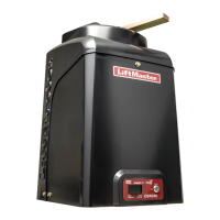
Electronic Box
19"
Top View of Chassis
Approximate placement of high voltage
and/or low voltage conduits.
To AVOID damaging operator, DO NOT weld
ANY supports to chassis. Chassis MUST be
allowed to flex during operation.
10.3"
10.4"
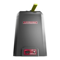
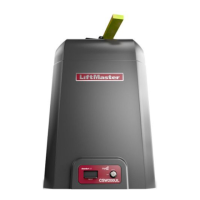
INSTALLATION
CONCRETE PAD AND ARM ATTACHMENT