41
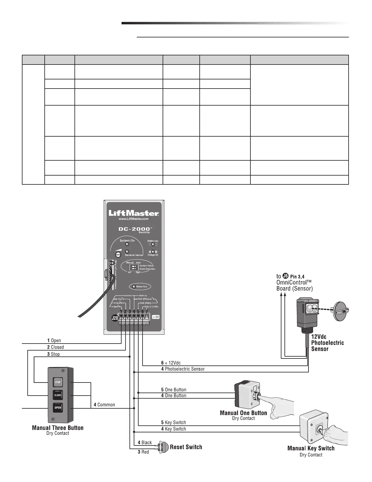
NOTE: All devices wired to the DC2000™ MUST be dedicated to
it alone. Normal operation will be controlled by separate devices
wired to the OmniControl™ board and surge suppressor.
N.O.
N.O.
N.O.
J #
J Pin # Signal Type Direction Level (+/- 10%) Input Connection
J20 1 Open N.O. Out 5 or 0 Vdc • Manual Three Button (Dry)
Reset Switch
2 Closed N.O.
Out
5 or 0 Vdc
3 Stop N.O.
Reset Switch
Out
5 or 0 Vdc
4 Common
Radio –
Radio Relay
Reset Switch
Out 0V
• Manual One Button (Dry)
• Key Switch (Dry)
• Reset Switch
5 One Button
Key Switch
Radio Relay
Out
0V
• Manual One Button (Dry)
• Key Switch (Dry)
6 Radio +12 Vdc
Photoelectric Sensor + 12 Vdc Out 12 or 0 Vdc
• Photoelectric Sensor 12 Vdc
7– –– –
WIRING DIAGRAMS
WIRING TABLE DC2000™