15
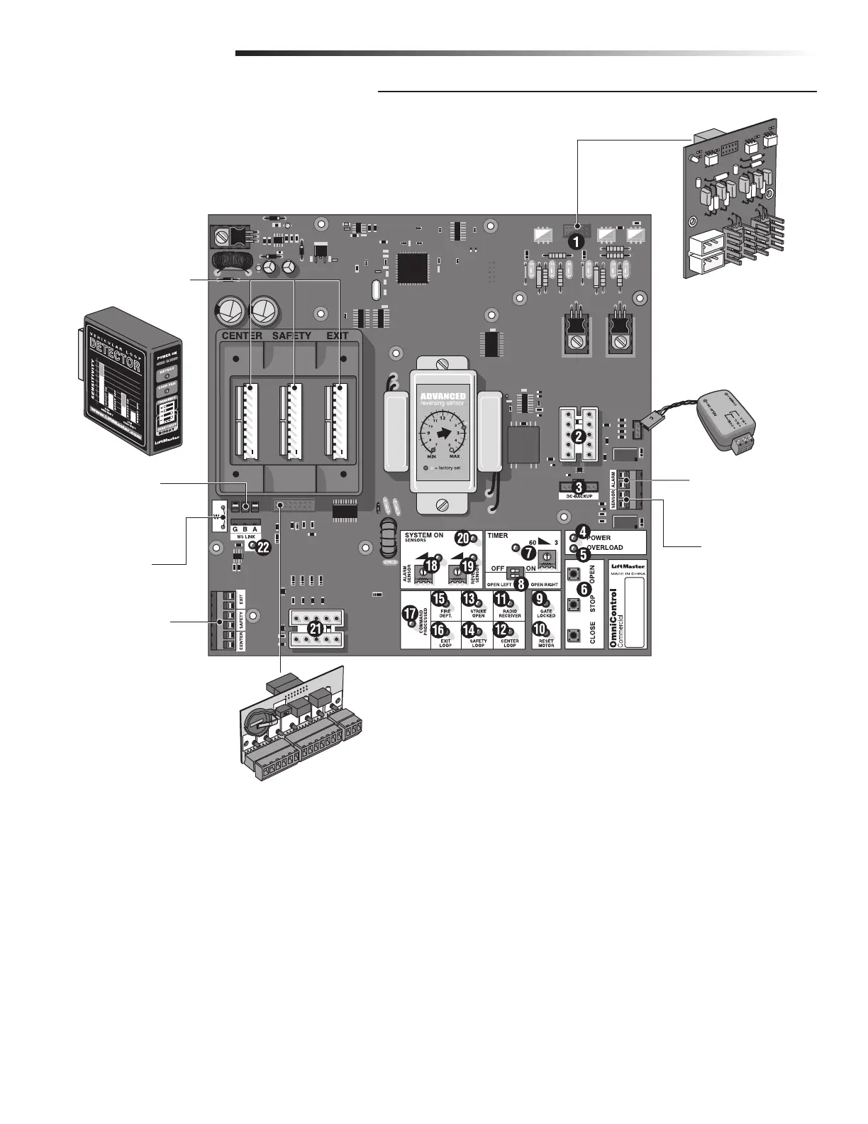
1. 1HP Connection - Factory installed CSW200UL1HP8™
Models.
2. J3 Motor, Limit Switch, Maglock/Solenoid Connection
3. DC2000™ Back-Up Power or Reset Switch Connection
4. Circuit Board Power LED - Operator power OK when ON.
5. Overload LED - Operator power has overloaded when ON.
6. On-Board 3 Button Station - Close, Stop, Open commands.
7. Timer - Timed close.
8. Gate Opening Direction Selector - Open Left, Open Right.
9. Gate Locked LED - Maglock/Solenoid is activated when on.
10. Reset Motor LED - Cycle operator power when ON.
11. Radio Receiver LED - Radio transmitter is activated when ON.
12. Center Loop LED - Center loop detector activated when ON.
13. Strike Open LED - Strike connected device activated when ON.
14. Safety Loop LED - Safety loop detector activated when ON.
15. Fire Dept LED - Key Switch activated when ON.
16. Exit Loop LED - Exit loop detector activated when ON.
17. Command Processed LED - Successful command executed.
18. Alarm Sensor - Limited Adjustment.
19. Reverse Sensor - Gate hit obstruction when ON.
20. System On LED - Operator is successfully performing a
command.
21. J1 Surge Suppressor Data Connection
22. M/S Link LED - Data being transferred between primary and
secondary operators when ON.
Maglock/Solenoid
Relay Module Connection
Plug-In Loop Wires
W4 Jumper Wire
UL Alarm Connection
Photoelectric
Sensor Connection
1 HP
Board
OmniControl™ Board Connection
Plug-In Loop Detectors
Surge Suppressor
Primary/Secondary
Connection
INSTALLATION
CONTROL BOARD DESCRIPTION