19
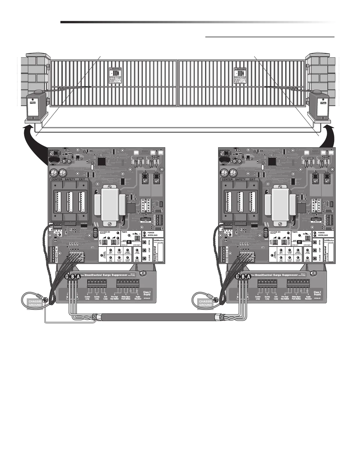
Run low voltage 16-18 gauge wire in UL approved conduit to link operators together.
Never run high voltage and low voltage wires in same conduit.
Use a 20 amp dedicated power circuit for each operator.
Primary Board
Secondary Board
Connect Primary M/S Link G to Second M/S Link G.
Connect Primary M/S Link B to Second M/S Link B.
Connect Primary M/S Link A to Second M/S Link A.
NOTE: Disconnect the second
radio receiver when using a
primary/secondary setup.
NOTE: To adjust
timers, see page 30.
Surge
Suppressor
Primary/
Secondary
Connection
Shield Wire
Primary/Secondary control boards are interchangeable.
In order for the following operation to occur, follow the instructions.
EXAMPLE: There is a double gate, the entry gate is to be opened with a remote control and the exit gate with a free exit loop. Only one
safety loop system is to open both gates, and a fire department switch should open both gates at the same time.
1. Connect the radio receiver to entry gate only.
2. Connect the exit loop to exit gate only.
3. Connect the safety loop to both entry and exit gates (observe polarity of voltage).
4. Connect the fire department switch to both entry and exit gates (observe polarity of both operators).
Use shielded
twisted wires for
M/S link.
Shield wire MUST
be grounded to
primary operator
Only.
Partial Primary/Individual Control
WIRING
LINKING PRIMARY/SECONDARY OPERATORS







 To Next Page