13
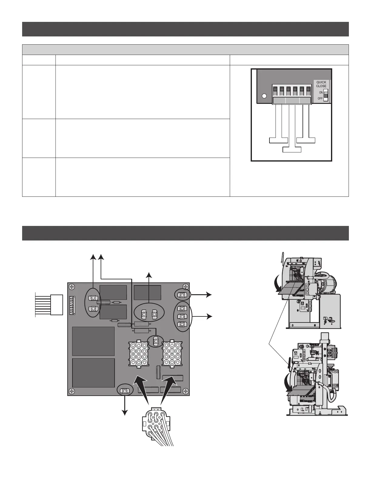
EXPANSION BOARD
LOOP INPUTS
INPUTS FUNCTIONALITY WIRING EXAMPLE
EXIT
Loop wire connection for plug-in loop detector when loop is inside secured area
near gate.
• Open command - opens a closed gate
• Soft open (maintained switch does not override external safeties and does
not reset alarm condition)
• If maintained, pauses Timer-to-Close at OPEN limit
• Opens a closing gate and holds open an open gate
SHADOW
Loop wire connection for plug-in loop detector when loop is positioned under
the gate.
• Holds open gate at open limit
• Disregarded during gate motion
• Pauses Timer-to-Close at Open Limit
INTERRUPT
Loop wire connection for plug-in loop detector when loop is on the outside of
the gate.
• Holds open gate at open limit
• Stops and reverses a closing gate
• Pauses Timer-to-Close at Open Limit
SHADOW INTERUPT EXIT
Exit Loop
Interrupt Loop
Shadow Loop
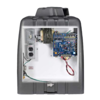
POWER BOARD
J9
PWR IN
TRANSFORMER
120V OUTLET
J11
J10
(BLACK) (WHITE)
J14
PWR IN
J1
(BLACK)
(WHITE)
J2
COMM
(WHITE)
120V
(GRAY)
240V
(PURPLE)
J8 J7
J6
START CAP
(RED)
RUN CAP
(ORANGE)
J13
J15
CAP
COMMON
(YELLOW)
120V 240V
J4
J5
TRANSFORMER
POWER
POWER
MOTOR HARNESS
(Factory Default 120V)
MOTOR DRIVE
(to main control board)
START CAP AND RUN CAP
ACCESSORY POWER OUTLET
NOTE: The power board
is located behind the
main control board.
This manual downloaded from http://www.manualowl.com

 Loading...