17
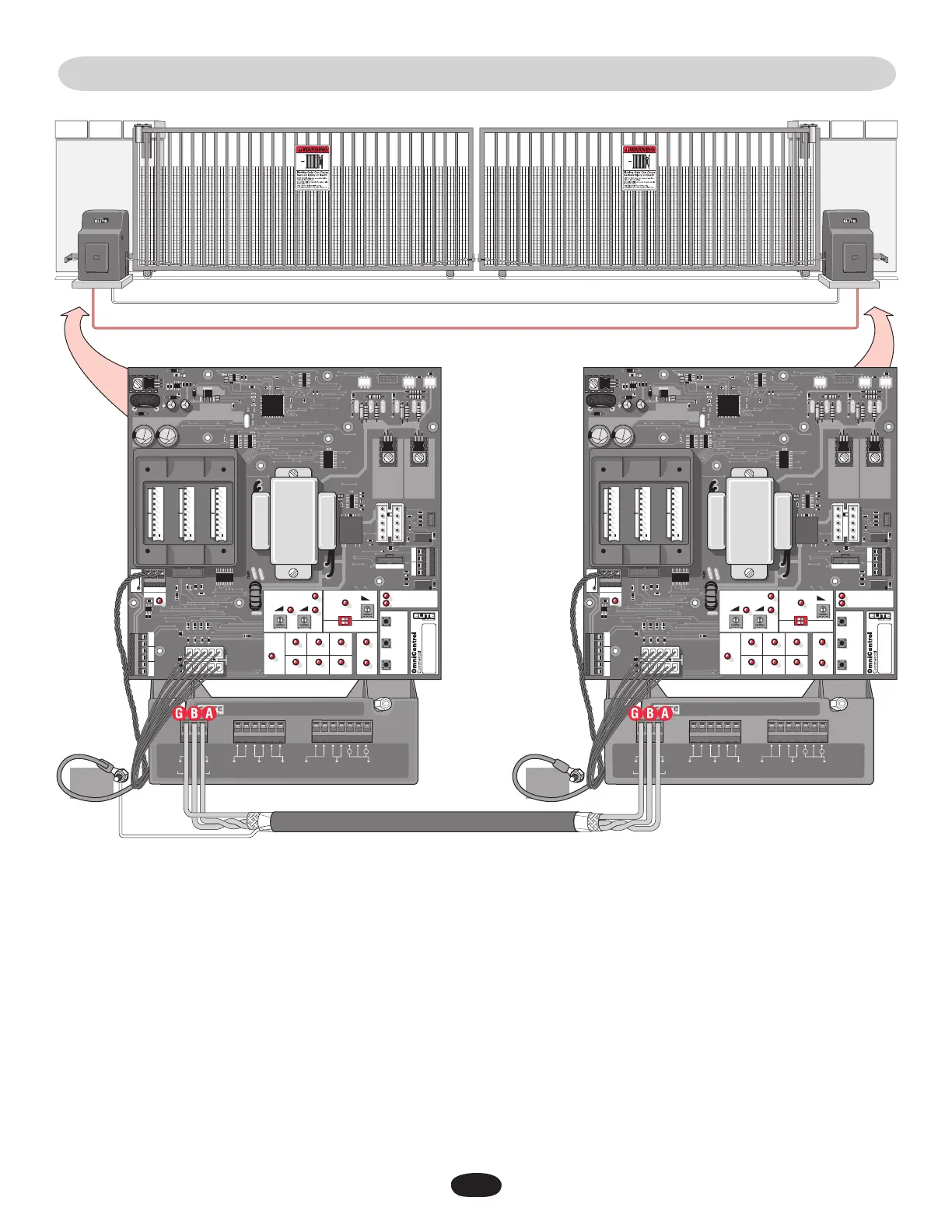
LINKING MASTER / SECOND OPERATORS
17
Strike Open
Push Button
Strike Open
Push Button
24 Volts DC24 Volts DC
Fire Dept
Key Switch
Fire Dept
Key Switch
M/S LinkM/S Link
Class 2
Supply
Class 2
Supply
Center
Loop
Center
Loop
Safety
Loop
Safety
Loop
Radio
Receiver
Radio
Receiver
Exit
Loop
Exit
Loop
GG
BB AA
––
++
OmniControl Surge Suppressor
P/N Q410
Patent Pending
P/N Q410
Patent Pending
®
CHASSIS
GROUND
Strike Open
Push Button
Strike Open
Push Button
24 Volts DC24 Volts DC
Fire Dept
Key Switch
Fire Dept
Key Switch
M/S LinkM/S Link
Class 2
Supply
Class 2
Supply
Center
Loop
Center
Loop
Safety
Loop
Safety
Loop
Radio
Receiver
Radio
Receiver
Exit
Loop
Exit
Loop
GG
BB AA
––
++
OmniControl Surge Suppressor
P/N Q410
Patent Pending
P/N Q410
Patent Pending
®
CENTER SAFETY EXIT
CENTER SAFETY EXIT
TIMER
SYSTEM ON
ALARM
SENSOR
OPEN
STOP CLOSE
60
POWER
OVERLOAD
OFF
W4
OPEN LEFT
DC-BACKUP
ALARM SENSOR
OPEN RIGHT
3
SENSORS
ON
G B
MS LINK
A
MADE IN USA
FIRE
DEPT.
STRIKE
OPEN
RADIO
RECEIVER
EXIT
LOOP
REVERSE
SENSOR
SAFETY
LOOP
CENTER
LOOP
GATE
LOCKED
RESET
MOTOR
COMMAND
PROCESSED
CENTER SAFETY EXIT
CENTER SAFETY EXIT
TIMER
SYSTEM ON
ALARM
SENSOR
OPEN
STOP CLOSE
60
POWER
OVERLOAD
OFF
W4
OPEN LEFT
DC-BACKUP
ALARM SENSOR
OPEN RIGHT
3
SENSORS
ON
G B
MS LINK
A
MADE IN USA
FIRE
DEPT.
STRIKE
OPEN
RADIO
RECEIVER
EXIT
LOOP
REVERSE
SENSOR
SAFETY
LOOP
CENTER
LOOP
GATE
LOCKED
RESET
MOTOR
COMMAND
PROCESSED
CHASSIS
GROUND
Run low voltage 16-18 gauge wire in UL approved conduit to link operators together.
Never run high voltage and low voltage wires in same conduit.
Use a 20 amp dedicated power circuit for each operator.
Master Board
Second Board
Connect Master M/S Link G to Second M/S Link G.
Connect Master M/S Link B to Second M/S Link B.
Connect Master M/S Link A to Second M/S Link A.
NOTE : Disconnect the second
radio receiver when using a
master/second setup.
NOTE: To adjust
timers, see page 29.
Surge
Suppressor
Master/
Second
Connection
Shield Wire
Master/Second control boards are interchangeable.
In order for the following operation to occur, follow the instructions.
Example: There is a double gate, the entry gate is to be opened with a radio transmitter and the exit gate with a free exit loop. Only one
safety loop system is to open both gates, and a fire department switch should open both gates at the same time.
1. Connect the radio receiver to entry gate only.
2. Connect the exit loop to exit gate only.
3. Connect the safety loop to both entry and exit gates. Plug-in loop detectors not applicable (Observe polarity of voltage).
4. Connect the fire department switch to both entry and exit gates (Observe polarity of both operators).
Use shielded
twisted wires for
M/S link.
Shield wire MUST
be grounded to
master operator
Only.
Partial Master/Individual Control