42
3 Red
4 Black
1 Open N.O. 6 + 12Vdc
5 Radio Relay
5 One Button
5 Key Switch
4 – Radio
4 One Button
4 Photoelectric Sensor
6 + 12Vdc
4 Key Switch
2 Close N.O.
3 Stop N.O.
4 Common
1 2 3 4 5 6 7
J20
1 2 3 4
Radio Receiver
315 MHz
12Vdc
to Pin 3,4
OmniControl™
Board (Sensor)
J6
Reset Switch
Manual Three Button
Dry Contact
Manual One Button
Dry Contact
Manual Key Switch
Dry Contact
12Vdc
Photoelectric
Sensor
12Vdc
Radio
Receiver
Red N.O.
Red N.O.
Black Com
Black Com
Interlock
Assembly
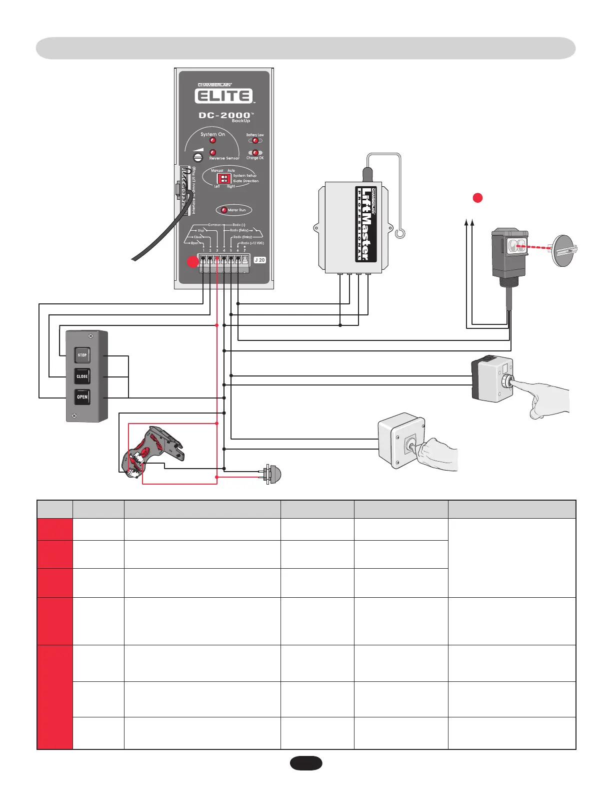
wiring tabLe • dc2000™
J20
J20
J20
J20
J20
J20
J20
1
2
3
4
5
6
7
Open N.O.
Close N.O.
Stop N.O.
Reset Switch
Common
Radio –
Radio Relay
Reset Switch/Interlock Assembly
One Button
Key Switch
Radio Relay
Radio + 12Vdc
Photoelectric Sensor + 12Vdc
–
5 or 0Vdc
5 or 0Vdc
5 or 0Vdc
0V
0V
12 or 0Vdc
–
Out
Out
Out
Out
Out
Out
–
• Manual Three Button (Dry)
Reset Switch
• Manual One Button (Dry)
• Key Switch (Dry)
• Radio Receiver
Reset Switch/Interlock Assy
• Manual One Button (Dry)
• Key Switch (Dry)
• Radio Receiver
• Radio Receiver 12Vdc
• Photoelectric Sensor 12Vdc
–
J # Direction Level (+/- 10%)J Pin #
Input Connection
Signal Type
NOTE: All devices wired to the DC2000™ MUST be dedicated to
it alone. Normal operation will be controlled by separate devices
wired to the OmniControl™ board and surge suppressor.
 Loading...