EasyManua.ls Logo

Chenbro RM23808 User Manual

Default Icon
71 pages
To Next Page IconTo Next Page
To Previous Page IconTo Previous Page
Page #30 background imageLoading...
Page #30 background image
RM238 Series
System Components Removal and Installation 30
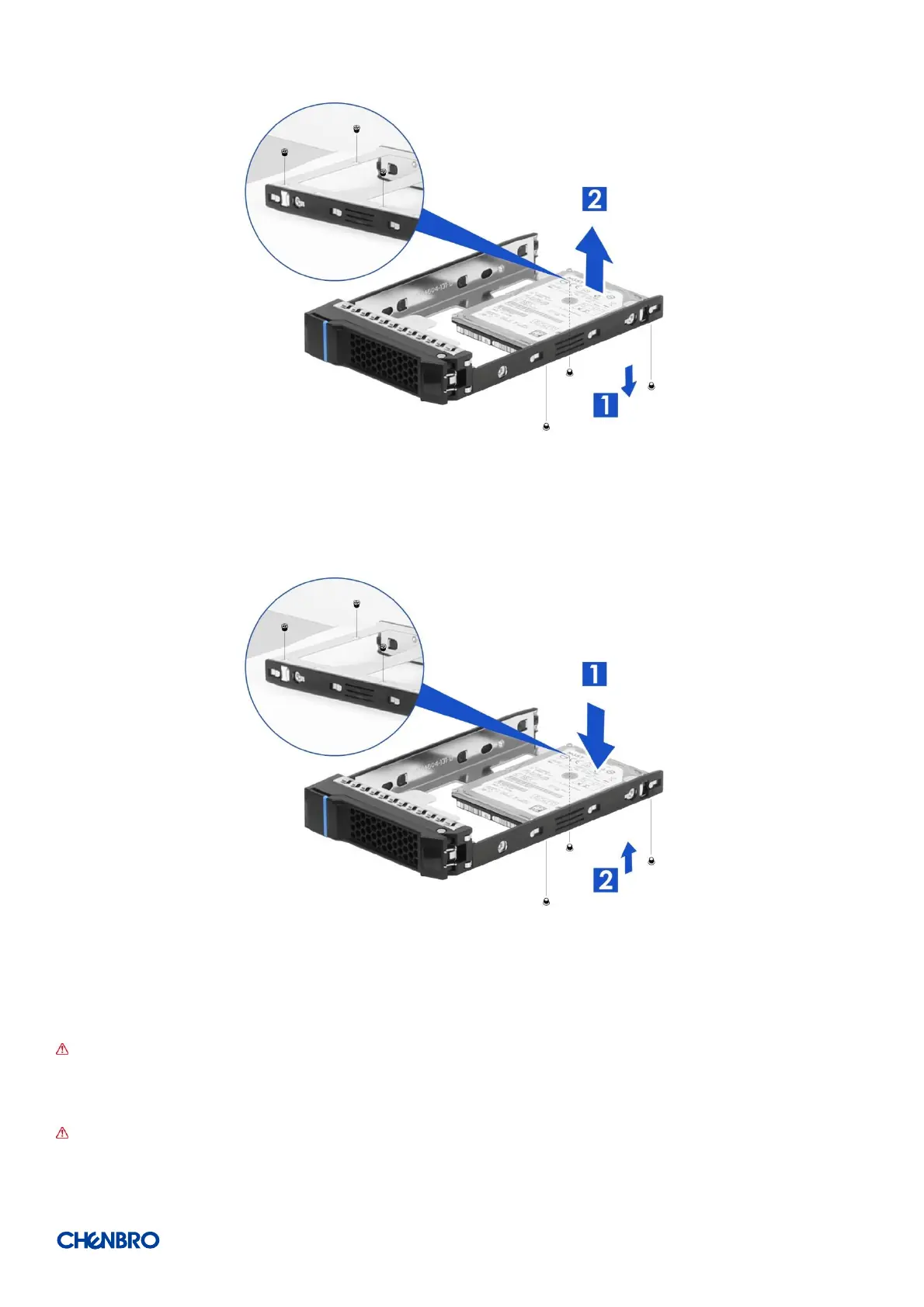
Figure 40 2.5’’ HDD removal in 3.5” tray (screw type)
1. Loosen three screws as shown.
2. Remove the HDD.
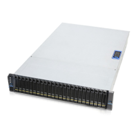
Figure 41 2.5’’ HDD installation in 3.5” tray (screw type)
1. Install the HDD in position on the tray.
2. Secure three screws as shown.
NOTE: To ensure proper system airflow requirements, all front drive bays are suggested to populate with a 3.5" drive tray where
it is supposed to be installed with a 3.5” drive, a 2.5” drive with plastic dummy filler or only dummy fillers. In addition, in order
to support a 2.5 drive in a 3.5 tray, a screw-type tray is required.
NOTE: Dedicated screw type is required for 2.5” SSD Installation, Chenbro P/N: 384-14602-3143A0.

Table of Contents

Question and Answer IconNeed help?

Do you have a question about the Chenbro RM23808 and is the answer not in the manual?

Chenbro RM23808 Specifications

General IconGeneral
BrandChenbro
ModelRM23808
CategoryChassis
LanguageEnglish

Summary

Disclaimers

Product Overview

System Features Overview

Overview of system features with diagrams and component labels.

Front Panel

Details the front panel layout, components, and controls.

Back Panel

Details the back panel layout, ports, and power supply connections.

Front Control Panel

Explains the front control panel buttons, LEDs, and connectors.

Storage Configurations

Illustrates different front drive bay configurations for various models.

Chassis Dimensions

Provides physical dimensions of the chassis and label embossing.

Available Rack Mounting Kit Options

Details options for rack mounting kits and compatibility.

System Level Environmental Specifications

Lists environmental specifications for operation and non-operation.

System Packaging

Information on system packaging, testing, and weight.

System Components Removal and Installation

Top Cover Removal and Installation

Instructions for removing and installing the chassis top cover.

HDD Cage Removal and Installation

Steps to remove and install the HDD cage assembly.

Hot-swap HDD Assembly Removal and Installation

Instructions for hot-swap HDD assembly removal and installation.

3.5" HDD Removal (Tool-less Type)

Steps for tool-less removal of 3.5" HDDs from trays.

3.5" HDD Removal (Screw Type)

Steps for screw-type removal of 3.5" HDDs from trays.

2.5" Hot-swap HDD Assembly Removal

Instructions for hot-swap 2.5" HDD assembly removal and installation.

2.5" HDD Removal (Tool-less Type)

Steps for tool-less removal of 2.5" HDDs from trays.

2.5" HDD Removal (Screw Type)

Steps for screw-type removal of 2.5" HDDs from trays.

2.5" HDD Removal in 3.5" Tray (Screw Type)

Instructions for removing 2.5" HDDs from 3.5" trays.

Internal 2.5" HDD Removal and Installation

Steps for removing and installing internal 2.5" HDDs.

Slim ODD Removal and Installation

Instructions for removing and installing a slim ODD.

System Maintenance

Procedures for removing and installing the entire system in a rack.

Fan Assembly Removal and Installation

Steps for removing and installing the main fan assembly.

Fan Module Removal

Instructions for removing and installing individual fan modules.

Air Baffle Removal

Steps for removing and installing the air baffle.

2.5" 2-bay Drive Cage Installation (Back Panel)

Instructions for installing a 2.5" 2-bay drive cage on the back panel.

Drive Backplane Installation (Back Panel)

Steps to install the drive backplane onto the back panel.

Full-height PCIe Card Installation

Instructions for installing full-height PCIe cards and riser cards.

PSU Installation and Removal

Steps for installing and removing the Power Supply Unit (PSU).

Redundant PSU Cage Assembly

Instructions for assembling and installing a redundant PSU cage.

CRPS Module Installation

Steps for installing and removing CRPS modules.

Slide Rail Installation

Instructions for installing slide rails for rack mounting.

Backplane

Storage Backplane Options

Lists the various storage backplane options available for the chassis.

3.5" 8-Port 12Gbps Mini-SAS HD Passive Backplane

Specifications and details for the 3.5" 8-port Mini-SAS HD passive backplane.

Backplane Connector and Pin Header Functions (3.5" 8-Port)

Describes connectors and pin headers for the 3.5" 8-port backplane.

RM23808 Fan Settings

Configuration details for fan settings on the RM23808 backplane.

3.5" 12-Port 12Gbps Mini-SAS HD Passive Backplane

Specifications for the 3.5" 12-port Mini-SAS HD passive backplane.

Backplane Connector and Pin Header Functions (3.5" 12-Port Passive)

Describes connectors and pin headers for the 12-port passive backplane.

Backplane Dip Switch Settings

Details the dip switch settings for backplane configuration.

3.5" 12-Port 12Gbps Mini-SAS HD Active Backplane

Specifications for the 3.5" 12-port Mini-SAS HD active backplane.

Backplane Connector and Pin Header Functions (3.5" 12-Port Active)

Describes connectors and pin headers for the 12-port active backplane.

Active Backplane Configuration Settings

Configuration settings for dip switches and fan for active backplane.

2 x 2.5" Drive Bay Accessory Kit

Details the 2 x 2.5" drive bay accessory kit and its usage.

SATA Backplane Specifications

Specifications for the SATA backplane.

Backplane Connector and Pin Header Functions (SATA)

Details connectors and pin headers for the SATA backplane.

OCuLink Backplane Specifications

Specifications for the OCuLink backplane.

Backplane Connector and Pin Header Functions (OCuLink)

Details connectors and pin headers for the OCuLink backplane.

2.5" 8-Port 12Gbps Mini-SAS HD Passive Backplane

Specifications for the 2.5" 8-port Mini-SAS HD passive backplane.

Mini-SAS HD Backplane Interface and Settings

Describes connectors, pin headers, and dip switch settings for the backplane.

2.5" 16-Port 12Gbps SAS Passive Backplane Docked with Expander Board

Specifications for the 2.5" 16-port SAS backplane with expander.

Backplane Connector and Pin Header Functions (2.5" 16-Port)

Details connectors and pin headers for the 16-port backplane.

Expander Board Specifications

Details the specifications of the expander board.

Expander Board Interface and Settings

Details connectors, pin headers, and dip switch settings for the expander board.

2.5" 8-Port SATA/SAS/NVMe (4 x Tri-mode) Passive Backplane

Specifications for the 2.5" 8-port SATA/SAS/NVMe backplane.

Backplane Connector and Pin Header Functions (2.5" 8-Port SATA/SAS/NVMe)

Details connectors and pin headers for the SATA/SAS/NVMe backplane.

2.5" 8-Port PCIe Gen3 NVMe Passive Backplane

Specifications for the 2.5" 8-port NVMe passive backplane.

Backplane Connector and Pin Header Functions (2.5" 8-Port NVMe)

Details connectors and pin headers for the NVMe backplane.

Maintenance and Service

DOA (Dead on Arrival)

Procedure for handling products found defective upon arrival.

Technical Support

Information required for technical support requests.

Related product manuals