RM238 Series
List of Figures│ 4
List of Figures
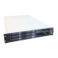
Figure 1 RM23808 overview .................................................................................................................... 9
Figure 2 RM23812 overview .................................................................................................................... 9
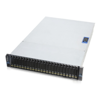
Figure 3 RM23824 overview .................................................................................................................... 9
Figure 4 RM23808 major components overview.................................................................................... 10
Figure 5 RM23812 major components overview.................................................................................... 10
Figure 6 RM23824 major components overview.................................................................................... 10
Figure 7 RM23808 front panel ............................................................................................................... 11
Figure 8 RM23812 front panel ............................................................................................................... 11
Figure 9 RM23824 front panel ............................................................................................................... 11
Figure 10 Back panel with single PSU ....................................................................................................... 12
Figure 11 Back panel with redundant PSU ................................................................................................ 12
Figure 12 Front control panel ................................................................................................................... 13
Figure 13 8 x 3.5” front drive bay configuration ....................................................................................... 14
Figure 14 12 x 3.5” front drive bay configuration...................................................................................... 14
Figure 15 24 x 2.5” front drive bay configuration (24 x SATA/SAS) ............................................................ 14
Figure 16 24 x 2.5” front drive bay configuration (4 x NVMe + 20 x SATA/SAS) ......................................... 15
Figure 17 24 x 2.5” front drive bay configuration (8 x NVMe + 16 x SATA/SAS) ......................................... 15
Figure 18 24 x 2.5” front drive bay configuration (20 x NVMe + 4 x SATA/SAS) ......................................... 15
Figure 19 24 x 2.5” front drive bay configuration (24 x NVMe) ................................................................. 15
Figure 20 Chassis dimensions ................................................................................................................... 16
Figure 21 Label embossing dimensions .................................................................................................... 16
Figure 22 Rear top cover removal ............................................................................................................ 21
Figure 23 Front top cover removal ........................................................................................................... 21
Figure 24 Front top cover installation ...................................................................................................... 22
Figure 25 Rear top cover installation ........................................................................................................ 22
Figure 26 HDD cage removal .................................................................................................................... 23
Figure 27 HDD cage installation ............................................................................................................... 23
Figure 28 3.5” hot-swap HDD assembly removal ...................................................................................... 24
Figure 29 3.5” hot-swap HDD assembly installation ................................................................................. 24
Figure 30 3.5” HDD removal (tool-less type) ............................................................................................ 25
Figure 31 3.5” HDD installation (tool-less type) ........................................................................................ 25
Figure 32 3.5" HDD removal (screw type) ................................................................................................. 26
Figure 33 3.5" HDD installation (screw type) ............................................................................................ 26
Figure 34 2.5" hot-swap HDD assembly removal ...................................................................................... 27
Figure 35 2.5’’ hot-swap HDD assembly installation ................................................................................. 27
Figure 36 2.5’’ HDD removal (tool-less type) ............................................................................................ 28
Figure 37 2.5’’ HDD installation (tool-less type) ........................................................................................ 28
Figure 38 2.5" HDD removal (screw type) ................................................................................................. 29