Installation Edge/Edge Blanket
2-8
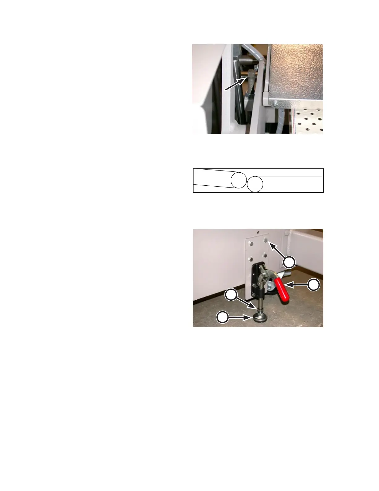
Figure 2-13: The locking floor pads help secure the
unit in position.
A
B
C
D
Remove and save the caster closest to the
Easi-Glide wheel.
Lower the endframe and remove the
jack.
Set the height of the ribbons using the
adjustment bolt in each discharge exten
-
sion arm (Figure 2-11) until the relative
positions are as shown in Figure 2-12.
Secure the unit in position by the appropri
-
ate method following local codes:
Set the locking casters.
Attach the provided locking floor pad
to the inside edge of the right endframe
(Figure 2-13, A). There is another one
each for the left endframe.
Adjust each pad so that it will rest
firmly against the floor when fully
extended (Figure 2-13, B). Secure the
adjustment by tightening the locking
nut (C).
Push the locking lever (Figure 2-13,
D) fully down to extend the pads and
firmly secure the unit in position.
OR
Secure the unit to its foundation if
required by local code. For use aboard
a ship, the unit may be welded at the
footpads. Always follow local codes.
Turn OFF the compressed air supply to
the unit.
9.
10.
11.
12.
•
•
•
•
•
13.
Figure 2-11: Ribbon height adjustment bolt
location.
Ironer inlet
Discha
rge
c
o
n
v
e
y
o
r
Figure 2-12: Proper positioning of the discharge
conveyor helps ensure smooth feeding.


 To Next Page