Operating Principles Edge/Edge Blanket
5-6
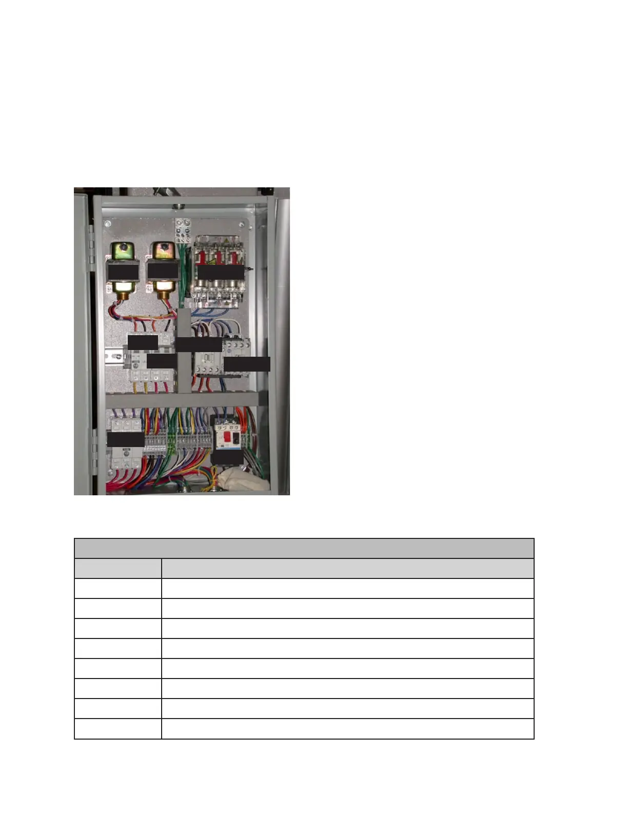
ELECTRICAL CONNECTION BOX COMPONENTS
Schematic Description
CB0 Circuit Breaker - T3 24VAC Control Circuit
CB1 Circuit Breaker - T4 24VAC Output Circuit
CB10 Circuit Breaker - Main Motor Circuit
CON8A/8B Contactor - Easi-Glide Motor Forward/Reverse (option)
DISC1 Main Disconnect Switch
MP8 Motor Protector - Easi-Glide Motor (option)
T3 Transformer - 24 VAC Control Circuit
T4 Transformer - 24VAC Output Circuit
Electrical Connection Box Panel
Components
Some power system components are located
in the electrical connection box (Figure 5-4) at
the right rear of the machine. The table below
provides an explanation of each item indicated
in the picture.
Figure 5-4: Components in the electrical
connection box.
T3
T4
CB0
CB1
CB10
MP8
CON8A
CON8B
DISC1