Installation
6
A
/
6
0
A
.
1
6
V
/
8
0
V
.
3
0
0
W
6
A
/
6
0
A
.
1
6
V
/
8
0
V
.
3
0
0
W
2
A
/
2
0
A
.
1
6
V
/
8
0
V
.
1
0
0
W
2
A
/
2
0
A
.
1
6
V
/
8
0
V
.
1
0
0
W
M
A
I
N
F
R
A
M
E
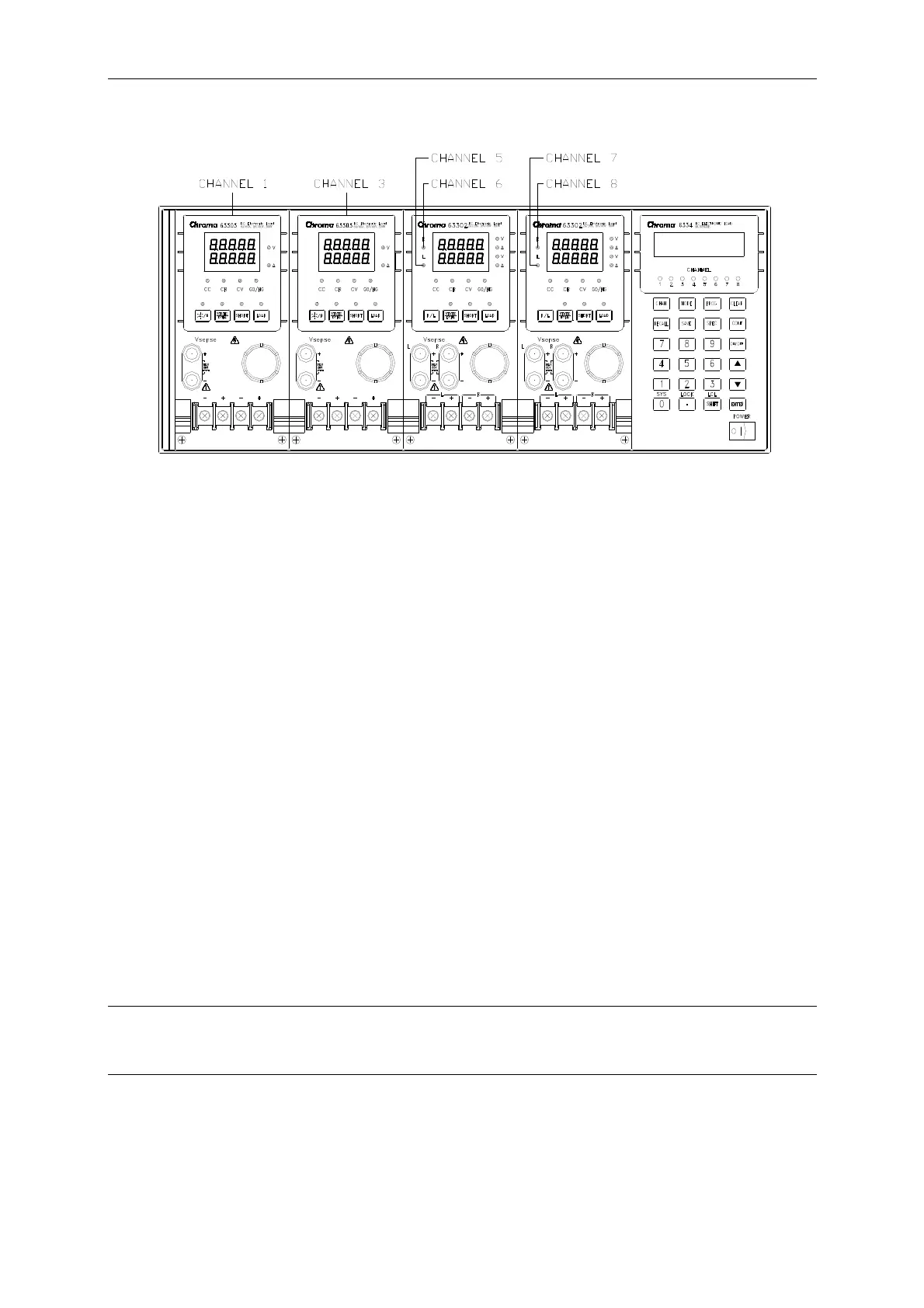
Figure 2-2 Example of Channel Number
2.4 Installing the Mainframe
The Electronic Load can operate well within temperature range from 0 to 40 degree C.
However, you must install the Electronic Load in an area that has enough space around for
adequate air flowing through and escaping from the back. You must leave at least 3 cm (1
inch) space above the unit for air circulation. Note that the unit foot stock has enough
vertical space for air circulation when it is stacked. The Mainframe foot stock can be
removed for rack mount.
If you install the equipment on top of your Electronic Load in a cabinet, you must use a filter
panel above the unit to ensure adequate air circulation. A 1U (EIA standard) panel is
sufficient.
2.4.1 Changing Line Voltage
The Electronic Load can operate with a 115/230 Vac input as indicated on the rear LINE label.
The 100/200 line voltage input model is for Japan only. If the factory set voltage does not
correspond to your nominal line voltage, turn off the Mainframe, and disconnect the power
cord. Set the switch to correct line voltage as shown in Figure 2-3.
L NOTICE
Line fuses do not need to be changed when the line voltage is changed. The line fuses will
protect the Electronic Load from incorrect voltage setting.
2-3

 Loading...
