Local Operation
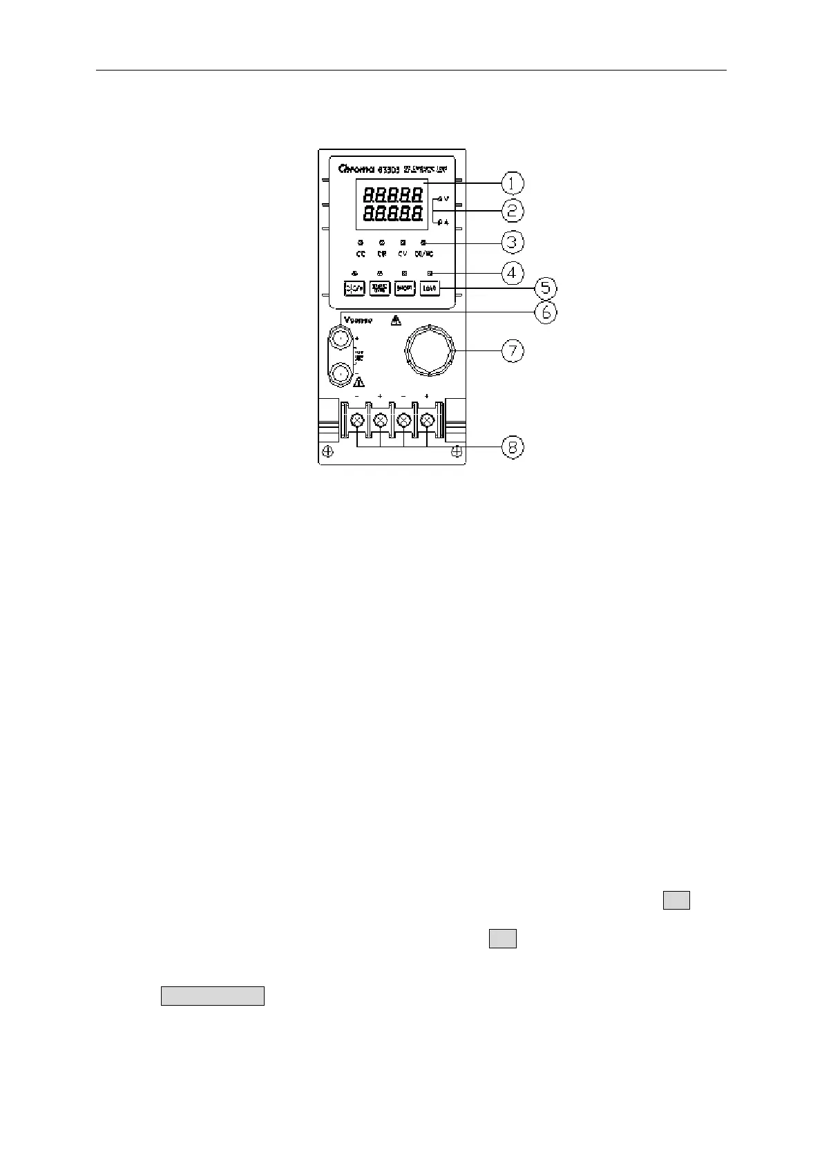
Figure 4-7 Single Channel/Module (Panel A)
4.3.1 Local Operation of Single Channel/Module (Panel A)
1. 7-segment LED Display
It displays the measurement Voltage and Current. Each display has five digits.
2. 7-segment Display Unit Indicators
They indicate the 7-segment display measurement unit V and I.
3. Operation Mode and GO/NG indicators
They indicate the operation modes of CC, CR, CV and GO/NG in the Load module.
GO/NG LED indicator has two colors. The green LED is on for GO (pass) while the
red is on for NG (fail). The GO/NG LED is off when SPEC test is OFF.
4. Keypad Indicators
The four LEDs indicate the keypad status. Each LED shows the key status under the
LED. Refer to the next paragraph for LED on/off status.
5. Keypad
There are four keys for you to select/control the operation of Load module. The A/B key
is used to select static load level. Its LED will be on when the Load is in level1 (A)
state and off when in level2 (B) state or others. The A/B key can be used to select fix
mode for rotary knob setting too. Please refer to 4.3.3.
The STATIC/DYNA key selects STATIC/DYNAmic mode. Its LED will be on when
the Load is in DYNAmic mode. DYNAmic operation is only effective in CC mode.
This key has no response in other modes.
4-19

 Loading...
